
Thermally-managed LED-based recessed down lights

a technology of led down lights and led bulbs, which is applied in the direction of semiconductor devices for light sources, fixed installations, lighting and heating apparatus, etc., can solve the problems of introducing unwanted color variations, failure, and relative short life, and achieves the effect of reducing the cost of production, and improving the quality of production

Active Publication Date: 2010-03-16
LIGHTING SCI GROUP
View PDF10 Cites 83 Cited by
  • Summary
  • Abstract
  • Description
  • Claims
  • Application Information

AI Technical Summary

Benefits of technology

"The LED down light replacement apparatus is designed to fit into a recessed-light housing can and includes an LED light source, a mounting mechanism, and a driver circuit. The apparatus also includes a heat sink and ventilation holes to remove the heat generated by the LED light source. The LED driver circuit converts AC current to constant DC current to drive the LED light source. The LED light source can include a plurality of blue LEDs coated with a phosphor or a combination of red, green, and blue LED arrays. The technical effects of this invention include improved energy efficiency, longer lifespan, and reduced maintenance costs compared to traditional lighting options."

Problems solved by technology

All three suffer from inefficiency, relatively short life, and high heat dissipation.
In addition, incandescent light sources use a thin filament which glows when heated by electrical power and tends to burn out easily.
If the wattage is raised to increase brightness, say to about 5-50 watts, the increased heat dissipation causes the LEDs to drift out of current-voltage specification, thereby introducing unwanted color variations and even failure.

Method used


Image

  • Thermally-managed LED-based recessed down lights
  • Thermally-managed LED-based recessed down lights
  • Thermally-managed LED-based recessed down lights

Examples


Embodiment Construction

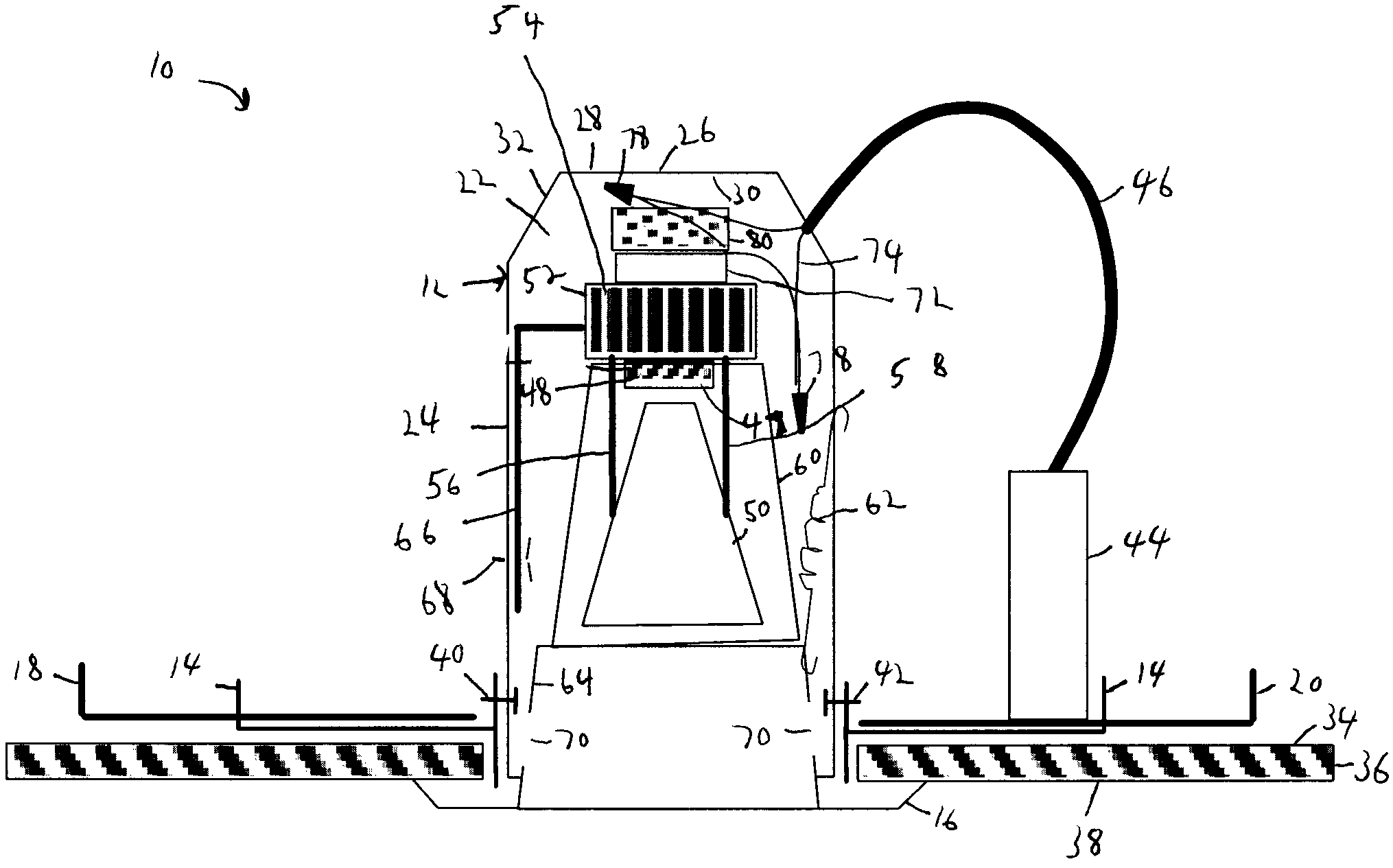
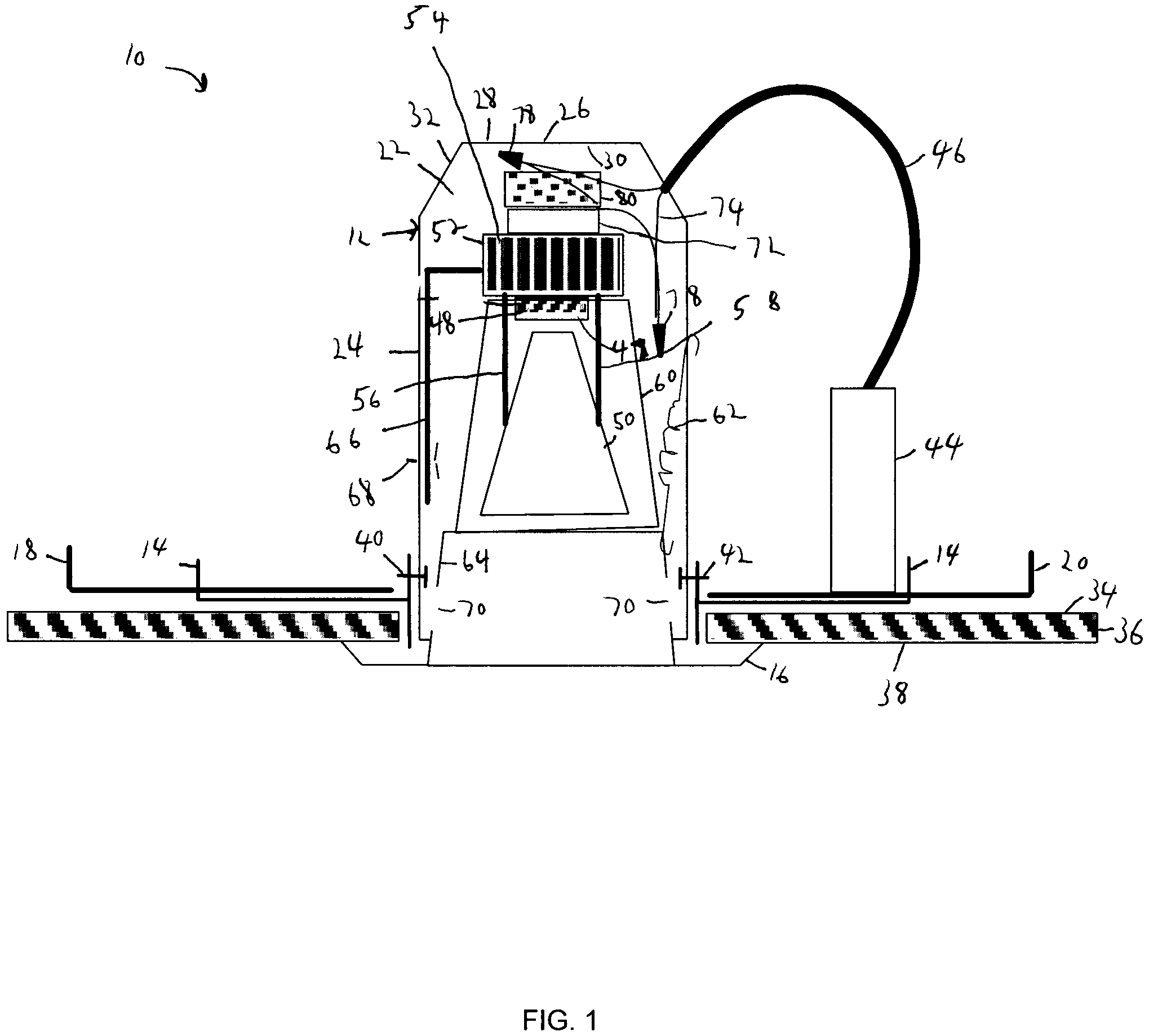
[0015]FIG. 1 is a schematic diagram of the structure of a retrofittable recessed LED down light fixture, according to an embodiment of the present invention, generally indicated at 10. The recessed lighting fixture 10 includes a housing can 12, base 14, generally annular trim 16, and mounting brackets 18, 20 interconnected as shown and defining an interior portion 22 of the lighting fixture 10. The housing can 12 includes a generally cylindrical wall portion 24 and circular top portion 26 having an upper surface 28 and a lower surface 30, connected by an angled truncated conical side portion 32. The mounting brackets 18, 20 are mounted between adjacent floor joists (not shown) with the base 14 resting on an upper surface 34 of a ceiling 36. The trim 16 extends from the can 12 and lies flush with a lower surface 38 of the ceiling 36. A pair of can-to-base attachment screws 40, 42 secure the base 14 to the mounting brackets 18, 20. A junction box 44 is mounted on the base 14 adjacent ...


PUM


Abstract

An LED down light replacement apparatus is disclosed for insertion into a recessed-light housing can, which includes an LED light source, a means for mounting said LED light source within the housing can, an LED driver circuit electrically connected to the LED light source, a heat sink in thermal contact with the LED light source, and means for removing heat generated by the LED light source. The means for removing heat generated by the LED light source can include a fan and / or ventilation holes in the top of the housing can.

Description

FIELD OF THE INVENTION[0001]The present invention relates generally to recessed lighting, and more particularly to an apparatus for retrofitting LED-based recessed lamps into incandescent or fluorescent recessed lighting fixtures.BACKGROUND OF THE INVENTION[0002]There are many types of lighting fixtures for the home or office which are known in the art. These include Edison based fixtures, surface mounted fixtures, track-lighting fixtures, and recessed fixtures. These fixtures have traditionally come in three types: incandescent, fluorescent, and high intensity discharge (HID) lights. All three suffer from inefficiency, relatively short life, and high heat dissipation. For example, incandescent lamps produce in the area of 14 to 17 lumens per watt. In addition, incandescent light sources use a thin filament which glows when heated by electrical power and tends to burn out easily. Typical, incandescent lamps have to be replaced every 2000 hours. Fluorescent lamps are an improvement o...

Claims


Application Information

Patent Timeline
Patent Type & Authority Patents(United States)
IPC IPC(8): F21S8/02
CPCF21S8/026F21V23/003F21V7/041F21V29/673F21V29/83F21Y2101/02F21V29/67F21Y2115/10
Inventor MAZZOCHETTE, JOSEPH B.
Owner LIGHTING SCI GROUP
Learn More