Drill and a drill cutting insert

a cutting insert and drill technology, applied in the direction of cutting inserts, twist drills, manufacturing tools, etc., can solve the problems of reducing the material thickness of the cutting insert, and the difficulty of adjusting the drill bi

Inactive Publication Date: 2010-03-16
SANDVIK INTELLECTUAL PROPERTY AB
View PDF9 Cites 26 Cited by
  • Summary
  • Abstract
  • Description
  • Claims
  • Application Information

AI Technical Summary

Benefits of technology

[0044]By the fact that the mouth surface of the hole has been given the trumpet-like, cross section-wise convex shape, the chips sliding along the topside of the cutting insert, and partly along the topside of the screw head, can pass fairly unresistingly in the backward direction from the chip-removing edge to the rear end of the cutting insert and further into the chip flute. This should be compared with the steep and sharp-edged mouth surface of the known cutting insert, which has formed an abrupt obstacle against which the chips have beaten and separated off minor component parts, which have been wedged into the space between the inside of the hole and the envelope surface of the screw head. The circumstance that the topside of the screw head is situated fairly near under the topside of the cutting insert (without for that reason sticking up itself from the last-mentioned one) also contributes significantly to the fact that the chips can smoothly pass the mouth surface of the hole in the new cutting insert. As a consequence of the new design of the hole of the cutting insert, also the width of the gap S has been reduced by the order of 30% (from 0.24 mm to 0.18 mm). This fact also contributes to minimizing the risk of bursting effect in the gap. Furthermore, it is emphasized that the problem with crack formation in the cutting insert has been possible to be solved without neither the screw nor the drill body having been needed to be modified.

Problems solved by technology

Specifically, problems have arisen in the type of drill which is disclosed in International Patent Publication Nos.
In practice, the construction of tools for chip removing or cutting machining involves a delicate compromising between conflicting desires.
Thus, on one hand it is desirable to use a heavy duty screw to anchor the cutting insert, but on the other hand a big screw would require a hole that reduces the material thickness of the cutting insert to such a great extent that the cutting insert becomes too weak to withstand the stresses acting on the same during mounting and drilling.
The fact is that, in practice, it would be very hard to keep a check on two different types of screws, even if the cutting inserts 2, 3 are different in respect of cutting edges and clearance surfaces.
This imposes particularly stiff requirements on the capability of the cutting inserts to form or break and guide the chips in an optimal way.
The chip evacuation from the center insert is particularly delicate as a consequence of the fact that infinitesimal points along the active cutting edge move at different periphery speeds in relation to the center axis of the drill.
This is one of the reasons for the head of the screw being countersunk under the topside of the cutting insert, because if the head should stick up, the same would be worn out quickly.
Therefore, the surprise was great when crack formation occurred in the center inserts of the smallest drills in the set.
The appearance of the cracks in this area was initially difficult to explain considering that this part of the cutting insert has a good support against the axial support surface 14.
However, this proved not to be the case.
However, careful examination showed that neither the spring bias force F2 (which may be approximately equally large as the cutting-force resultant)—neither as viewed separately nor in combination with the cutting-force resultant F1—could give rise to the cracks.

Method used


Image

  • Drill and a drill cutting insert
  • Drill and a drill cutting insert
  • Drill and a drill cutting insert

Examples


Embodiment Construction

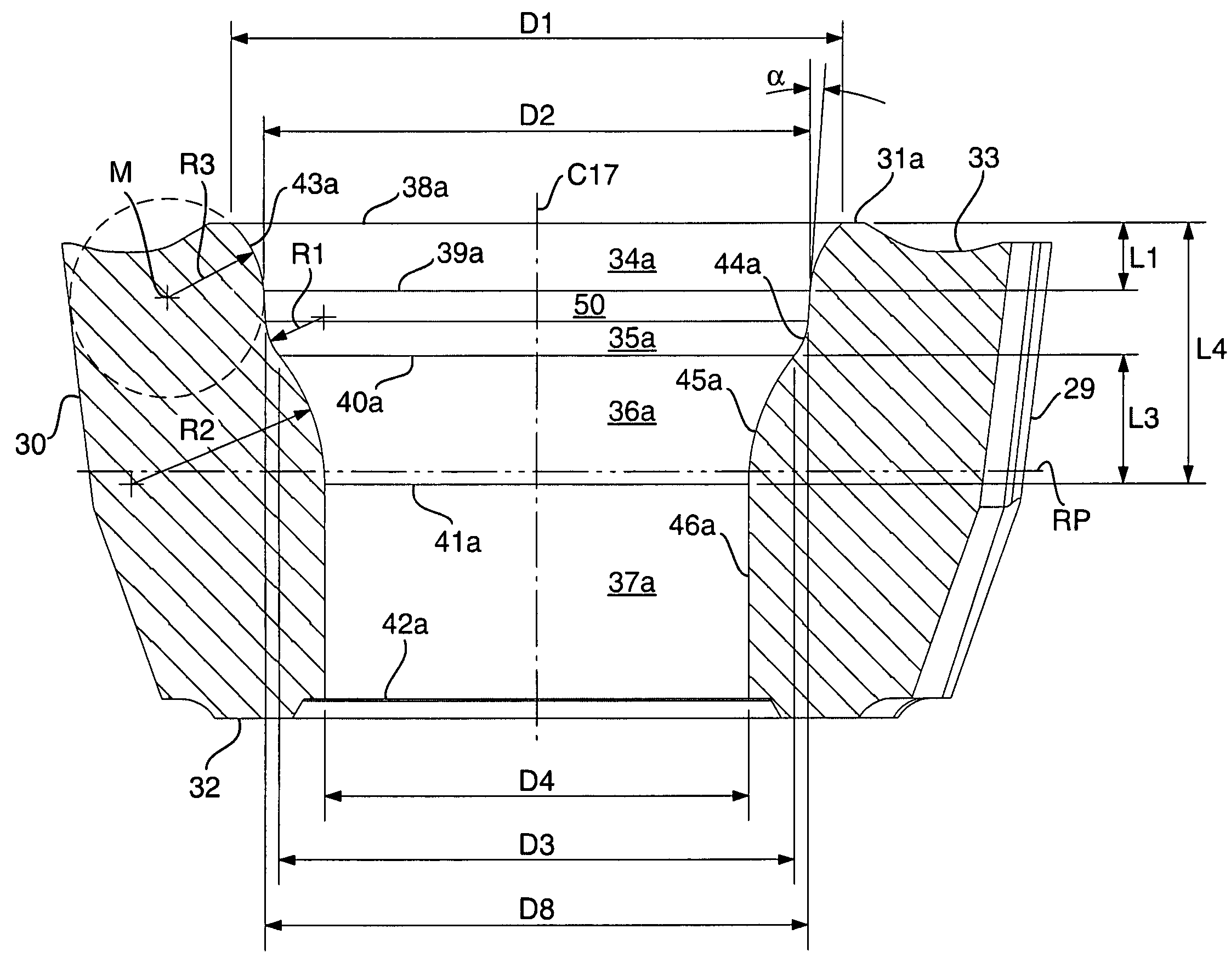
[0035]A hint to overcoming the deficiencies of the prior art drills was obtained when tracks or marks from the chips were discovered on the mouth surface 34. From this discovery, the conclusion was drawn that the numerous chips during the passage thereof above the screw head beat against the mouth surface. The beating of the extremely hot chips against the mouth surface by itself applies extraordinary mechanical forces to the rear part of the cutting insert. Furthermore, fragments of the chips are likely to be separated and forced into the wedge-shaped tapering gap S between the envelope surface 22 of the screw head and the upper part of the hole 17 (see FIGS. 4 and 5). If the chip fragments are pressed down by a great force into the gap, a wedge action arises that leads to the cracking of the cutting insert.

[0036]Based on the above-mentioned insight, the problem has been solved in the way that is seen in FIGS. 6-8, viz. by making the mouth surface 34 in the hole 17 of the cutting i...


PUM

PropertyMeasurementUnit
angleaaaaaaaaaa
thicknessaaaaaaaaaa
diameteraaaaaaaaaa

Abstract

A drill for chip removing machining, including a drill body, and a replaceable cutting insert mounted in a pocket formed in a front tip of the drill body. A chip flute extends backwardly from the pocket along the drill body, and the cutting insert is fixed in the pocket by a screw including a head and a shank having a male thread. The cutting insert includes a through hole extending between a topside and an underside. The hole has a basic shape that is rotationally symmetrical in relation to a center axis, and is delimited by a series of surfaces including a mouth surface, converging downward from the topside, and a shoulder surface. The head of the screw is kept pressed against the shoulder surface when the male thread of the screw is tightened in a female thread included in a hole that mouths in a bottom of the pocket. The mouth surface in the hole of the cutting insert has a trumpet-like, cross section-wise convex shape adjacent to the topside of the cutting insert.

Description

[0001]This application claims priority under 35 U.S.C. §119 to Sweden Patent Application No. 0600217-4, filed on Jan. 30, 2006, the disclosure of which is incorporated by reference herein in its entirety.FIELD OF THE INVENTION[0002]The present invention relates generally to a drill for chip removing machining of the type that includes a drill body, and a replaceable cutting insert which is mounted in a pocket formed in a front tip of the drill body. A chip flute extends rearwardly along the drill body from the pocket. The cutting insert is fixed in the pocket by means of a screw which includes a head and a shank having a male thread. The cutting insert includes a through hole extending between a topside and an underside. The hole has a basic shape that is rotationally symmetrical in relation to a center axis, and is delimited by a series of surfaces including a mouth surface, converging downward from the topside, and a shoulder surface. The head of the screw is kept pressed against ...

Claims


Application Information

Patent Timeline
Patent Type & Authority Patents(United States)
IPC IPC(8): B23B51/02
CPCB23B27/1622B23B51/02B23B2200/0423B23B2200/204B23B2200/3618Y10S408/713Y10T408/90993Y10T408/89Y10T408/905Y10T407/1936Y10T408/909B23B47/34
Inventor LIMELL, MICHAELWIKBLOM, TORBJORN
Owner SANDVIK INTELLECTUAL PROPERTY AB
Why Eureka
Try Eureka