Vibration motor

a vibration motor and motor body technology, applied in the field of vibration motors, can solve the problems of over-the-counter vibration motors, prior-art vibration motors have a disadvantage of low reliability against shock, and vibration motors have a structure that is not suitable, so as to improve impact resistance and reduce the effect of deflection and increase the rigidity

Inactive Publication Date: 2010-03-16
SANYO SEIMITSU
View PDF8 Cites 11 Cited by
  • Summary
  • Abstract
  • Description
  • Claims
  • Application Information

AI Technical Summary

Benefits of technology

[0010]Since the metal holder frame does not have the pair of sandwiching pieces having a domal structure rising up from both-side edges of a flat bottom part, and the motor case has a cylindrical shape to be inserted in the axial direction to be held, the holding of the motor case does not tend to leave from the metal holder frame even when a shock is generated. In addition, since the spacer projections of the plastic end cap are inserted between the motor case and the both-end edges of the flat bottom part by wedge pressure, the holding of the motor case does not tend to be loosened so that the impact resistance can be improved. When the motor case having the round circumferential surface is inserted into the metal holder frame, the circumference if the motor case will elastically run on the inside projection so as to be tightly fastened by the motor case with the round circumferential surface can be fixed and held.
[0011]It is preferable that the metal holder frame integrally comprises tapered projections each having a rectangular cross section, the tapered projections being projected to the both sides of the eccentric weight from the both-side edges of the flat bottom part. When the vibration motor is mounted on the printed wiring board, the vibration motor can be prevented from being fallen forward by the heavy eccentric weight due to the supporting function of the tapered projections. In addition, the fixing area can be expanded. In particular, since each of the tapered projections has the rectangular cross section, the rigidity against deflection becomes high so that any deformation due to bent over of the tapered projections when a shock is generated can be prevented

Problems solved by technology

However, the above vibration motor has had the following problems.
Therefore, the prior-art vibration motor has a disadvantage of low reliability against shock.
Therefore, the vibration motor has a structure not suitable for the use of a motor case with a round circumferential surface.

Method used


Image

  • Vibration motor
  • Vibration motor
  • Vibration motor

Examples


Embodiment Construction

[0020]Preferred embodiments of the present invention will be described in detail below while referring to the attached figures.

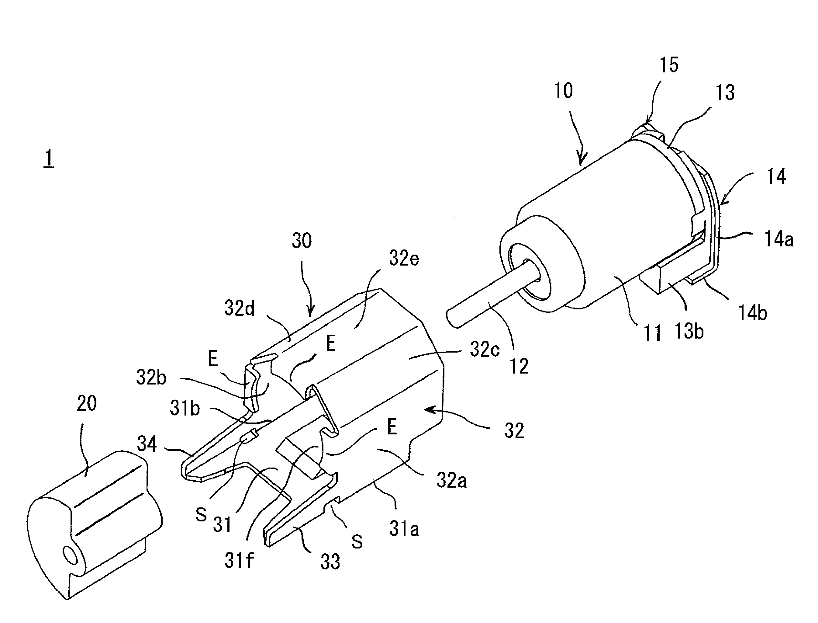
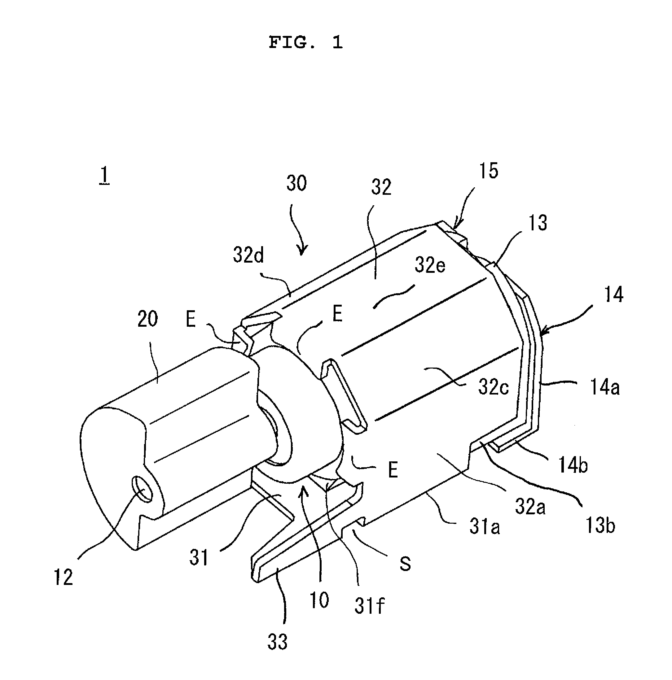
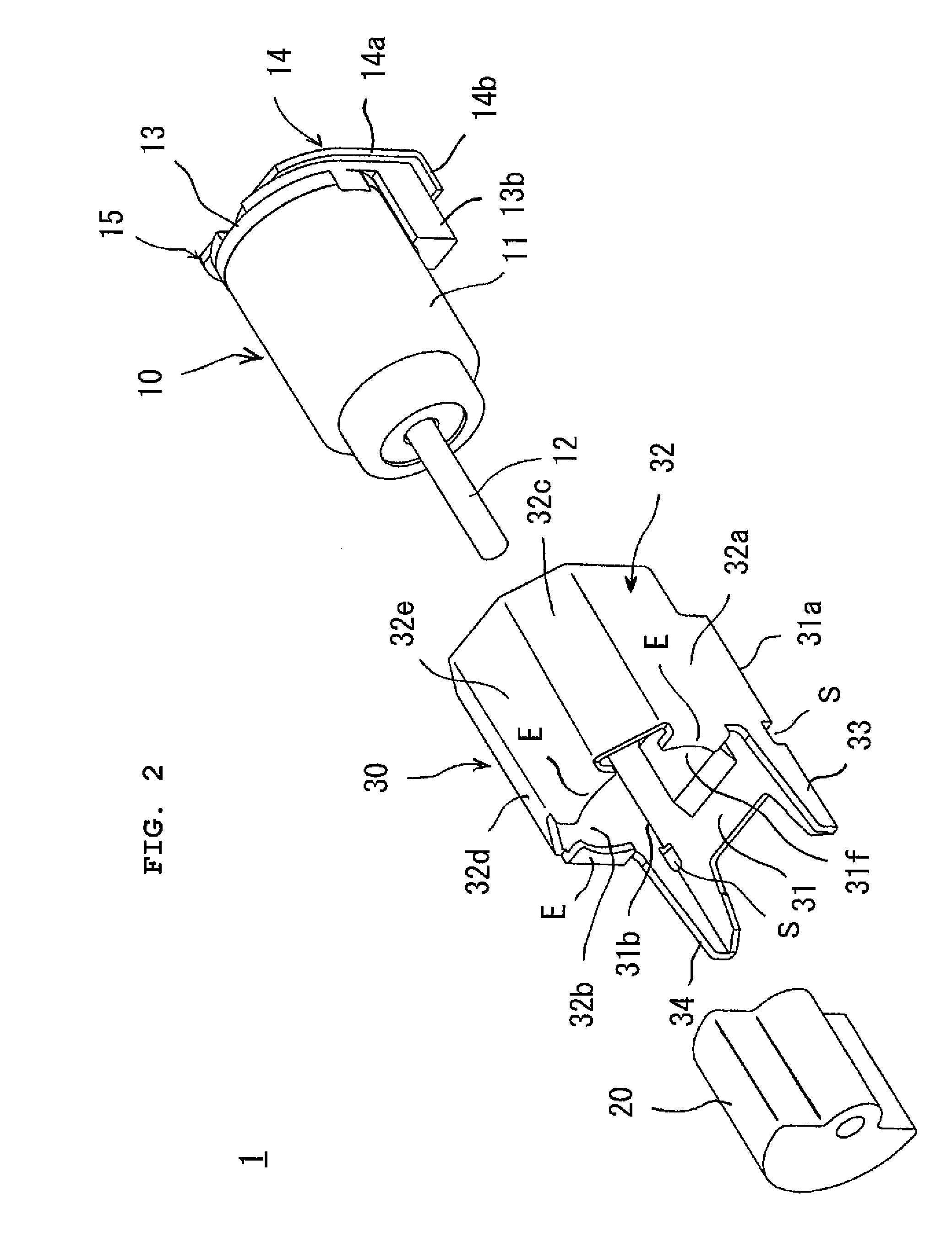
[0021]As shown in FIGS. 1 to 4, the vibration motor11 of this example has a motor main body 10, an eccentric weight 20, and a metal holder frame 30. The motor main body 10 is provided with a motor shaft 12 projected from one end of a motor case 11 having a round-shaped circumferential surface and a pair of external terminal pieces 14 and 15 attached to a plastic end cap (end bracket) 13 for covering an aperture at the other end of the motor case 11. The eccentric weight 11 is attached to the projected motor shaft 12. The metal holder frame 30 has a tubular shape and is provided with a wall surface 32 having a domal structure rising up from both-side edges 31a and 31b of a flat bottom part 31.

[0022]The metal holder frame 30 is obtained by press forming of one metal plate. The flat bottom part 31 is a surface which is to be adhered to a fixing pattern of a pri...


PUM


Abstract

A vibration motor having an eccentric weight 20 includes a tubular metal holder frame 30 with a flat bottom part 31 and a wall surface 32, the flat bottom part 31 having an inner projection 31f with a bottom-up recess part W, the upper wall surface 32 being domed; a pair of external terminal pieces 14 and 15 attached to a plastic end cap 13, wherein the plastic end cap 13 has spacer projections 13b and 13c inserted between the motor case 11 and the flat bottom part 31.

Description

CROSS-REFERENCE TO RELATED APPLICATIONS[0001]This application is based upon and claims a priority of Japanese Patent Application No. 2007-243592, filed Sep. 20, 2007, the contents being incorporated herein by reference.BACKGROUND OF THE INVENTION[0002]1. Field of the Invention[0003]The present invention relates to a vibration motor suitable for mounting on a printed circuit board by reflow soldering.[0004]2. Description of the Related Art[0005]As a vibration motor of a structure suitable for surface mounting on a printed circuit board, as disclosed in Japanese Patent Publication (A) No. 11-234943, there is known one having a motor body with an eccentric weight attached to one end of a motor shaft, a metal holder frame provided with a pair of sandwiching pieces for fitting a motor case of the motor body from its upper portion and holding that motor case, and a pair of external terminal pieces attached to a plastic end cap for closing an opening of the motor case at the side opposite ...

Claims


Application Information

Patent Timeline
Patent Type & Authority Patents(United States)
IPC IPC(8): H02K7/06
CPCH02K5/00H02K5/04H02K7/061H02K2211/03H05K3/301
Inventor KONO, KENJI
Owner SANYO SEIMITSU
Why Eureka
Try Eureka