Method and microscope for high spatial resolution examination of samples

a high spatial resolution, microscope technology, applied in the field of methods and microscopes, can solve the problems of time-consuming scanning operation and interference pattern of interference beams

Inactive Publication Date: 2010-03-16
LEICA MICROSYSTEMS CMS GMBH
View PDF22 Cites 17 Cited by
  • Summary
  • Abstract
  • Description
  • Claims
  • Application Information

AI Technical Summary

Benefits of technology

[0008]It is now an object of the present invention to specify a method and a microscope of the type mentioned at the beginning which enable rapid scanning of a sample with structurally simple and cost effective means in conjunction with a compact design.
[0012]The method according to the invention and the microscope according to the invention can be used in a particularly advantageous way in conjunction with first and second states that are very long lasting or are even temporally stable permanently. In this case, it is possible to select for the saturation of the transition from the first into the second state a comparatively long period within which the energy of the optical signal that is required for saturation is irradiated. The local intensities relating to transitional saturation can thereby be selected to be very slight. Above all, the total energy available from a radiation source of the optical signal can be distributed over voluminous regions in the sample space, and a number of intensity zero points, or an extended zero point can be produced. The saturation can be achieved despite the low local intensities resulting therefrom in the vicinity of the zero point(s) by comparison with the application of the total signal around only one punctiform zero point. This requires that the signal be irradiated only for a sufficiently long time until all the molecules in the surroundings of the zero points are finally in the second state. This is a decisive difference from the case of a shortlived state (for example in the STED method with a typical lifetime of ˜1 ns for a fluorescence-capable state A), where the energy required for saturation must be irradiated in such a short time (substantially faster than the rate A→B) that the total power of the radiation source is sufficient only to produce one (or at most a few) local zero points. It may be demonstrated for concrete systems that it is possible in the case of stable states (for example photochromic dyes) or long lived states (for example transfer into the triplet system in the case of the GSD, GSD=Ground State Depletion, method) for the power of cost effective and commercial laser systems to be distributed over such large regions that a number of punctiform intensity zero points (>>10) or entire stripes of vanishing intensity, in the immediate vicinity of which saturation can be achieved as before, can be produced in the sample. This enables a parallelized imaging when the sample is simultaneously scanned with the multiplicity of punctiform zero points or with zero point lines, and the signals are detected simultaneously for each zero point in a separate fashion by a detector. In this way, it is possible to design microscopes with resolutions below the classic diffraction limit, their imaging rate being in the region of STED-based methods, and being substantially increased by comparison with systems with a single local zero point.
[0018]With regard to a particularly compact design, the optical component for producing the pupil line, and the phase modulating element could be arranged as a structural unit in the illuminating beam path. With regard to a high degree of flexibility, the optical component for producing the pupil line, and the phase modulating element could also, however, be arranged as separate units at different positions in the illuminating beam path.
[0020]In a particularly advantageous way, the light of the optical signal is polarized perpendicular to the pupil line in order in this way to exclude depolarization effects to a maximum extent.
[0023]It is provided in a further preferred design that the optical signal and a test signal are respectively generated in order to read out the first state by means of pulsed light sources. A synchronization of the pulsed light sources proves to be advantageous in this case.

Problems solved by technology

It is disadvantageous in the known methods that the interfering beams form an interference pattern with local punctiform intensity minima.
Consequently, scanning the sample requires a point-to-point scanning operation in at least two dimensions, and this renders the scanning operation extremely time consuming.

Method used


Image

  • Method and microscope for high spatial resolution examination of samples
  • Method and microscope for high spatial resolution examination of samples
  • Method and microscope for high spatial resolution examination of samples

Examples


Embodiment Construction

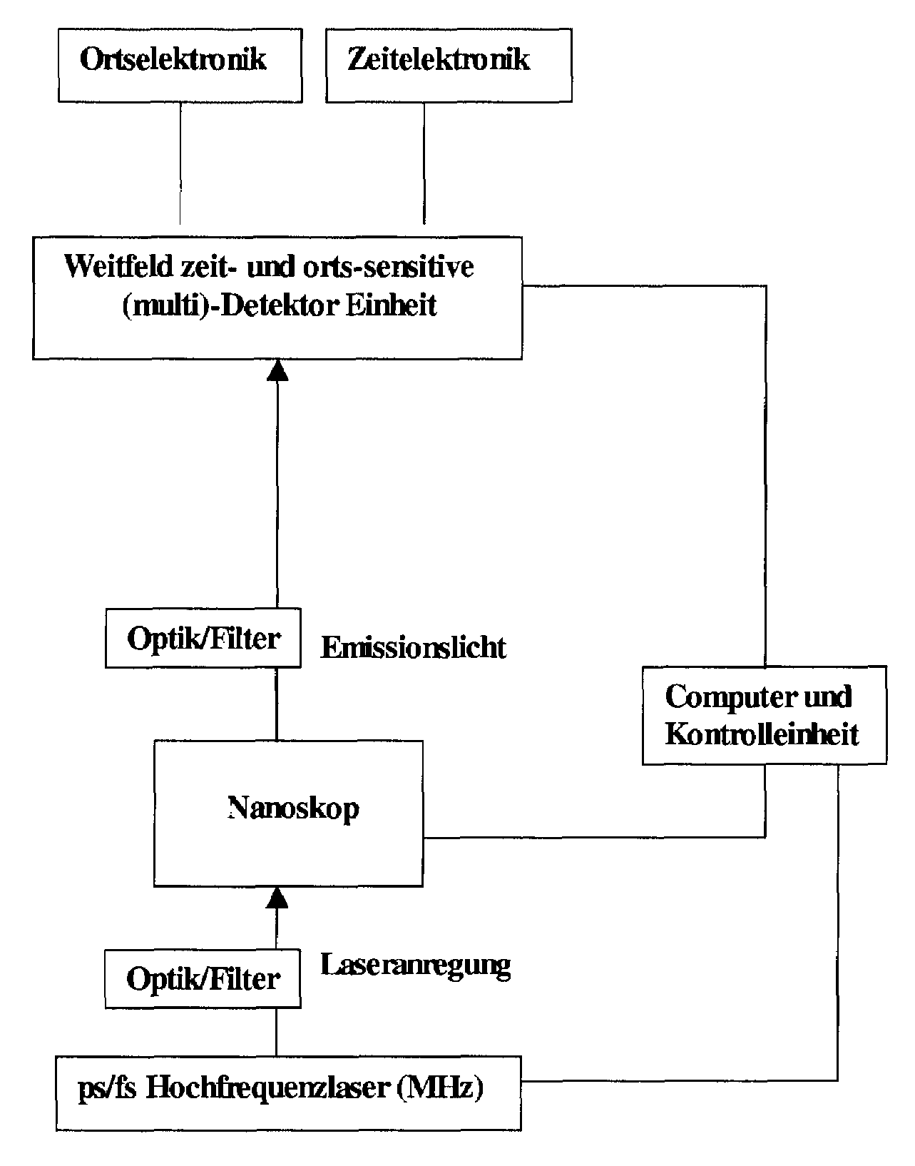
[0036]FIG. 1 shows a schematic of a cyclic illumination operation such as is used for high spatial resolution examination of samples beyond the diffraction limited resolving limit. In accordance with FIG. 1a, the first step is to use a switching signal 2 to bring into the first state Z1 in the entire sample space P to be recorded a substance that is provided in the sample 1 and can be converted repeatedly from a first state Z1 into a second state Z2, the first and the second states Z1, Z2 differing from one another in at least one optical property. In the exemplary embodiment illustrated in concrete terms, the first state Z1 is a fluorescing state A, and the second state Z2 is a nonfluorescing state B. In the example illustrated in concrete terms, the substance provided in the sample 1 is a photochromic substance whose molecules are brought into the fluorescence-capable state A by irradiation with light of a first wavelength, the switching signal 2. This happens ideally by illuminat...


PUM


Abstract

A method and a microscope, in particular a laser scanning fluorescence microscope, for high spatial resolution examination of samples, the sample (1) to be examined comprising a substance that can be repeatedly converted from a first state (Z1, A) into a second state (Z2, A), the first and the second states (Z1, A; Z2, B) differing from one another in at least one optical property, comprising the steps that the substance in a sample region (P) to be recorded is firstly brought into the first state (Z1, A), and that the second state (Z2, B) is induced by means of an optical signal (4), spatially delimited subregions being specifically excluded within the sample region (P) to be recorded, are defined in that the optical signal (4) is provided in the form of a focal line (10) with a cross-sectional profile having at least one intensity zero point (5) with laterally neighboring intensity maxima (9).

Description

CROSS-REFERENCE TO RELATED PATENT APPLICATIONS[0001]The right of foreign priority is claimed under 35 U.S.C. § 119(a) based on Federal Republic of Germany Application No. 10 2006 009 831.5, filed Mar. 1, 2006, the entire contents of which, including the specification, drawings, claims and abstract, are incorporated herein by reference. The present application also claims benefit of priority to U.S. Provisional Application Ser. No. 60 / 853,447, filed Oct. 23, 2006, the entire contents of which is incorporated herein by reference.BACKGROUND OF THE INVENTION[0002]The invention relates to a method and a microscope, in particular a laser scanning fluorescence microscope, for high spatial resolution examination of samples, the sample to be examined comprising a substance that can be repeatedly converted from a first state into a second state, the first and the second states differing from one another in at least one optical property, comprising the steps that the substance in a sample regi...

Claims


Application Information

Patent Timeline
Patent Type & Authority Patents(United States)
IPC IPC(8): G01J3/30
CPCG02B21/0076G02B27/58
Inventor DYBA, MARCUSGUGEL, HILMAR
Owner LEICA MICROSYSTEMS CMS GMBH
Why Eureka
Try Eureka