Supercharge Your Innovation With Domain-Expert AI Agents!

Disc adjustment system for chipper apparatus

a disc chipper and adjustment system technology, applied in the field of wood chippers, can solve the problems of relatively complex assembly of the disc chipper apparatus

Active Publication Date: 2010-03-23
CEM MACHINE
View PDF9 Cites 5 Cited by
  • Summary
  • Abstract
  • Description
  • Claims
  • Application Information

AI Technical Summary

Benefits of technology

The solution enables safer, faster, and more precise adjustments, reducing the need for multiple operators and simplifying the process, while being adaptable to existing chippers, with the worm gear providing a high mechanical advantage for fine adjustments in small increments.

Problems solved by technology

These assemblies are relatively complex and also require separate and various loosening and tightening procedures in order to effect adjustment.

Method used


Image

  • Disc adjustment system for chipper apparatus
  • Disc adjustment system for chipper apparatus
  • Disc adjustment system for chipper apparatus

Examples


Embodiment Construction

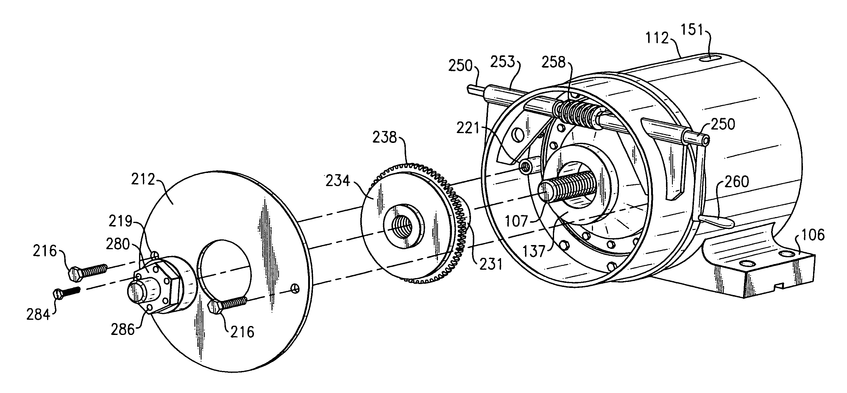
[0031]The following description relates to an exemplary embodiment of a disc adjustment mechanism for a rotary chipper apparatus. Throughout the course of discussion that follows, certain terms such as “top”. “bottom”, “lateral”, “axial”, “distal”, “proximal” and the like are used in order to provide a convenient frame of reference with regard to the accompanying drawings. These terms are not intended to be specifically limiting, except where so specifically indicated.

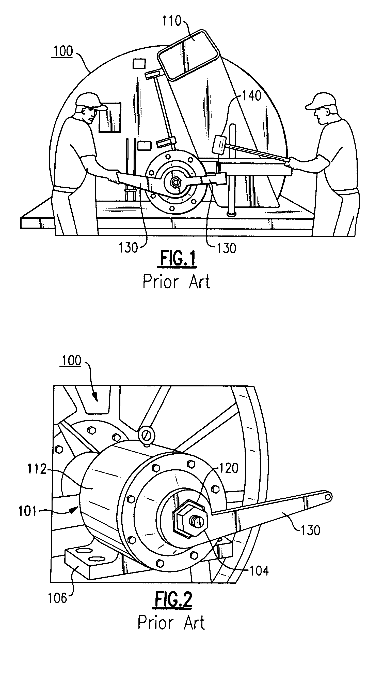
[0032]Reference is first made to FIGS. 1-3 and FIGS. 9 and 10 to provide additional background and detail of operation relating to a prior art chipper apparatus for purposes of the present invention.

[0033]Referring briefly to FIGS. 9 and 10, a chipper apparatus is shown, the apparatus including an adjustment mechanism of the cutting disc 102 that is provided on one side of the apparatus wherein the cutting disc 102 is supported on each side of the chipper apparatus. Though FIGS. 9 and 10 each illustrate a rotary chippe...


PUM


Abstract

An adjustment mechanism for a rotary disc chipper apparatus includes an axially displaceable shaft attached to a chipper disc, at least one gear disposed in relation to the axially adjustable shaft and a drive member engageable with the at least one gear to produce axial movement of the axially displaceable shaft and the chipper disc.

Description

FIELD OF THE INVENTION[0001]This invention relates to wood chippers and more particularly to a system and a related method for adjusting the blade clearance in a disc chipper apparatus.BACKGROUND OF THE INVENTION[0002]A chipper apparatus or “chipper” is used in the field of lumber pulp production to process logs and to cut them or “chip” them into smaller pieces. In so-called “disc” chippers, a large rotary disc retains a series of radially disposed cutting knives on a facing surface of the disc. This disc can be adjusted in relation to a stationary cutting knife, commonly referred to by those of ordinary skill in the field as a “bedknife” or “anvil”.[0003]The large rotary disc is usually mounted for rotation onto a shaft that is driven by either an electric or diesel motor that may be coupled to a gear box. The chipper disc and shaft are held by two (2) large bearings. These bearings are affixed to the driven shaft, but are allowed to move axially in their respective housings. An e...

Claims


Application Information

Patent Timeline
Patent Type & Authority Patents(United States)
IPC IPC(8): B02C1/08B02C7/14
CPCB27L11/005B27L11/02
Inventor MCBRIDE, DANIEL R.
Owner CEM MACHINE
Features
  • R&D
  • Intellectual Property
  • Life Sciences
  • Materials
  • Tech Scout
  • Unparalleled Data Quality
  • Higher Quality Content
  • 60% Fewer Hallucinations
Learn More