Working method and cleaning device to clean a swimming pool

a cleaning device and working method technology, applied in the direction of cleaning process and equipment, water/sludge/sewage treatment, construction, etc., can solve the problems of increasing the deviation of the original direction of motion (path direction), accumulating path errors, and affecting the quality of swimming pool cleaning process, so as to improve the quality and reliability of the swimming pool cleaning process. , the effect of improving the precision

Active Publication Date: 2010-03-23
3S SYSTTECHN AG
View PDF6 Cites 17 Cited by
  • Summary
  • Abstract
  • Description
  • Claims
  • Application Information

AI Technical Summary

Benefits of technology

[0005]The object of this invention is to provide a working method for a swimming pool cleaning device of this type that allows for further improvement in the precision with which the cleaning paths are maintained (motion pattern stability), and thus further improves the quality and reliability of the swimming pool cleaning process. The working method is intended to be equally suitable both for large rectangular swimming pools as well as for swimming pools of an irregular shape.

Problems solved by technology

However, it has been found that in swimming pool cleaning devices of this type, gradually increasing deviations from the direction of motion (path direction) originally established nevertheless very often occur.
Investigations have shown that each time the cleaning devices run up to an edge of the swimming pool or an obstacle, the jolt caused by abrupt braking or impact usually causes a backward displacement or a rotation, albeit only slightly.
As the number of abrupt braking motions increases, these path errors accumulate.
For the most part, mechanical devices continue to be used as contacting means since other sensors, such as those that are optics based, rapidly fail or provide unreliable results especially in turbid water.

Method used


Image

  • Working method and cleaning device to clean a swimming pool
  • Working method and cleaning device to clean a swimming pool
  • Working method and cleaning device to clean a swimming pool

Examples


Embodiment Construction

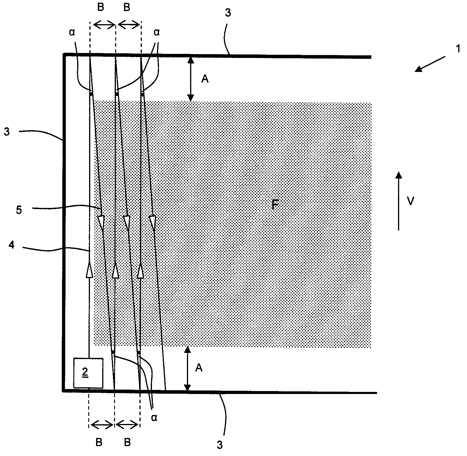
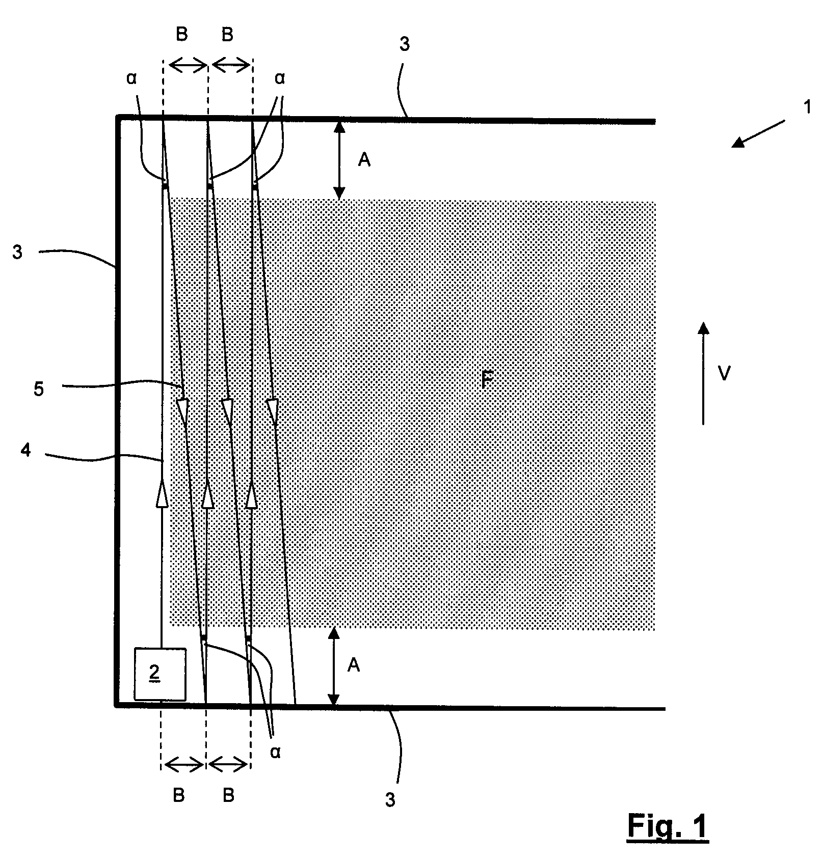
[0025]To begin with, a cleaning device 2 that moves back and forth in the swimming pool 1 is placed in a start position in a corner at a swimming pool wall 3. The cleaning device 2 is directed such that when it is released it moves in a forward direction V in a first cleaning path 4 parallel to a swimming pool wall 3.

[0026]The cleaning device 2 has a drive mechanism that can be switched to forward or backward travel and is actively connected to drive wheels or drive tracks, with a motor being provided for each of a left-hand side and a right-hand side part of the drive mechanism, respectively, a control apparatus to control the drive mechanism, and contact means arranged at the front and rear to generate control signals in the event that the cleaning device runs up to a swimming pool wall 3 or an obstacle. The control apparatus has a speed control device for each part of the drive mechanism as well as means for differential control of the speed of the two motors in the respective pa...


PUM


Abstract

In a working method for a cleaning device (2) that moves back and forth in a swimming pool (1), control thereof is such thatthe cleaning device (2) moves from a starting position at a low speed in a forward direction V in a first pass in a first cleaning path (4) until it runs up to a pool wall (3), wherein the distance D1 traversed along the first cleaning path is measured or determined,the cleaning device (2) is then guided to a second cleaning path (5) deviating from or offset relative to the first cleaning path (4) in a second pass, initially at a low speed, whereupon the cleaning device then moves in a backward direction along the second cleaning path (5) at a high speed until the distance Dz traversed is smaller than the distance D1 traversed in the previous pass by an amount A,upon reaching distance Dz the cleaning device (2) continues to move along the second cleaning path (5) at low speed until it runs up to a swimming pool wall (3), wherein the distance D2 traversed along the second cleaning path is measured or determined, andthe cleaning device (2) is controlled in the same manner in each subsequent pass as in the previous pass.

Description

FIELD OF THE INVENTION[0001]The invention relates to a working method for a cleaning device according to patent claim 1 that moves back and forth in a swimming pool and to a cleaning device according to patent claim 9 to carry out the working method.BACKGROUND OF THE INVENTION[0002]In particular, the invention relates to a cleaning device that moves back and forth in a swimming pool, said cleaning device having a drive mechanism that can be switched to forward or backward travel and that is actively connected to drive wheels or drive tracks, with a motor being provided for each of a left-hand side and a right-hand side part of the drive mechanism, respectively. Also provided is a control apparatus to control the drive mechanism, and contact means arranged at the front and rear to generate control signals in the event that the cleaning device runs up to a swimming pool wall or an obstacle. In addition, the control apparatus includes a speed control unit for each part of the drive mec...

Claims


Application Information

Patent Timeline
Patent Type & Authority Patents(United States)
IPC IPC(8): B08B7/04
CPCE04H4/1654
Inventor SOMMER, HANS RUDOLFSOMMER, PETER
Owner 3S SYSTTECHN AG
Why Eureka
Try Eureka