Display driving apparatus and multi-line inversion driving method thereof

a driving apparatus and display technology, applied in the direction of instruments, static indicating devices, etc., can solve the problems of increasing reducing so as to reduce the power consumption of source drivers and reduce the polarity switching frequency

Inactive Publication Date: 2010-03-23
NOVATEK MICROELECTRONICS CORP
View PDF3 Cites 9 Cited by
  • Summary
  • Abstract
  • Description
  • Claims
  • Application Information

AI Technical Summary

Benefits of technology

[0010]An objective of the present invention is to provide a display driving apparatus, which adopts a multi-line inversion driving method to lower the polarity switching frequency for the sub-pixel driving signal output by the source driver, thereby reducing the power consumption of the source driver.
[0011]Another objective of the present invention is to provide a multi-line inversion driving method, wherein every time after a plurality of scan lines is turned on sequentially, the polarity of the sub-pixel driving signal is inverted, so as to reduce the power consumption of the source driver.
[0013]Another objective of the present invention is to provide a display, wherein the switching frequency of the data line between positive and negative polarities is lowered, so as to reduce the power consumption of the display driving apparatus, and the turn-on time for each scan line is adjusted, thereby solving the problem of a frame with non-uniform brightness due to different charging times of the sub-pixels.
[0016]The period that every N scan lines are sequentially turned on by the gate driver is an N-line period. In each N-line period, a first turn-on time of the first scan line is not equal to a second turn-on time of the second scan line, wherein the first turn-on time or the second turn-on time is controlled by a plurality of latch signals output by the latch signal unit. The value of N is determined by the line polarity signal output by the line polarity signal unit. The above-mentioned gate enabling signal respectively adjusts the turn-on time for each scan line during the polarity inversion period of the sub-pixel driving signals, thereby solving the unequal charging problem for each sub-pixel via adjusting the charging time.
[0019]As the present invention adopts a multi-line inversion driving method, after a plurality of scan lines is sequentially turned on, the polarities of the sub-pixel driving signals are inverted once, so as to lower the inversion frequency of the data lines between positive and negative polarities, thereby reducing the power consumption of the source driver. Further, the turn-on time for each scan line is adjusted to make each sub-pixel obtain a sufficient charging time during the polarity inversion of the sub-pixel driving signal, thereby avoiding the phenomenon of non-uniform brightness.

Problems solved by technology

Thin film transistor liquid crystal displays (TFT LCDs) have become one of the main streams of flat panel displays (FPDs), and source drivers are among the major power consumption for TFT LCD driving apparatuses.
As such, the power consumption of the source driver becomes greater.
With the coming of a high pixel era, in order to maintain the frame quality, a higher polarity inversion frequency for sub-pixels is needed, which may cause greater power consumption.

Method used


Image

  • Display driving apparatus and multi-line inversion driving method thereof
  • Display driving apparatus and multi-line inversion driving method thereof
  • Display driving apparatus and multi-line inversion driving method thereof

Examples


Embodiment Construction

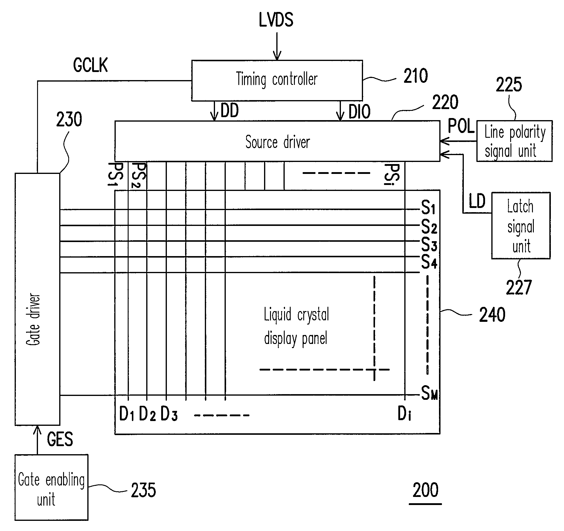
[0039]FIG. 2 is an architectural view of a display according to an embodiment of the present invention. As shown in FIG. 2, the display of the present embodiment comprises a timing controller 210, a source driver 220, a line polarity signal unit 225, a latch signal unit 227, a gate driver 230, a gate enabling unit 235 and a liquid crystal display panel 240.

[0040]The timing controller 210 is electrically connected to the gate driver 230 and outputs a gate clock signal GCLK for controlling the output timing of the gate driver 230. The gate driver 230 is electrically connected to scan lines S1˜SM in the liquid crystal display panel 240. Each of the scan lines S1˜SM has a plurality of sub-pixels, wherein M is a positive integer. The gate enabling unit 235 is electrically connected to the gate driver 230, and provides a gate enabling signal GES to the gate driver 230 for controlling the gate driver 230 to determine the turn-on time for each scan line.

[0041]The timing controller 210 is fu...


PUM


Abstract

A display driving apparatus and a multi-line inversion driving method thereof are provided. The apparatus includes a gate driver, a source driver, a gate enabling unit and a line polarity signal unit. Every time after a plurality of scan lines is turned on, the source driver inverts the polarity of the sub pixel driving signal according to a line polarity signal output by the line polarity signal unit. Thereby, the polarity inversion operating frequency of the sub pixel driving signal is lowered to reduce the power consumption of the source driver.

Description

CROSS-REFERENCE TO RELATED APPLICATION[0001]This application claims the priority benefit of Taiwan application serial no. 95116504, filed May 10, 2006. All disclosure of the Taiwan application is incorporated herein by reference.BACKGROUND OF THE INVENTION[0002]1. Field of Invention[0003]The present invention relates to a display driving apparatus, and more particularly, to a display driving apparatus applicable for driving a liquid crystal display panel and a multi-scan line inversion driving method thereof.[0004]2. Description of Related Art[0005]Thin film transistor liquid crystal displays (TFT LCDs) have become one of the main streams of flat panel displays (FPDs), and source drivers are among the major power consumption for TFT LCD driving apparatuses.[0006]At present, large panels are generally driven by dot inversion, and the largest power consumption thereof is related to the polarity inversion frequency of the scan lines, wherein the greater the frequency is, the more power...

Claims


Application Information

Patent Timeline
Patent Type & Authority Patents(United States)
IPC IPC(8): G09G3/36
CPCG09G3/3614G09G3/3648G09G2310/027G09G2310/08
Inventor JAN, CHUNG-JRLIN, CHE-LI
Owner NOVATEK MICROELECTRONICS CORP
Why Eureka
Try Eureka