
Solid state storage subsystem for embedded applications

a storage subsystem and embedded technology, applied in computing, electrical equipment casings/cabinets/drawers, instruments, etc., can solve the problems of consuming a significant amount of board real estate within the host system, the hardware used to implement the ide interface so as to reduce the amount of board real estate used to carry interface signals the complexity of the board layout in the host system, the effect of reducing the amount of board

Active Publication Date: 2010-03-23
WESTERN DIGITAL TECH INC
View PDF13 Cites 158 Cited by
  • Summary
  • Abstract
  • Description
  • Claims
  • Application Information

AI Technical Summary

Benefits of technology

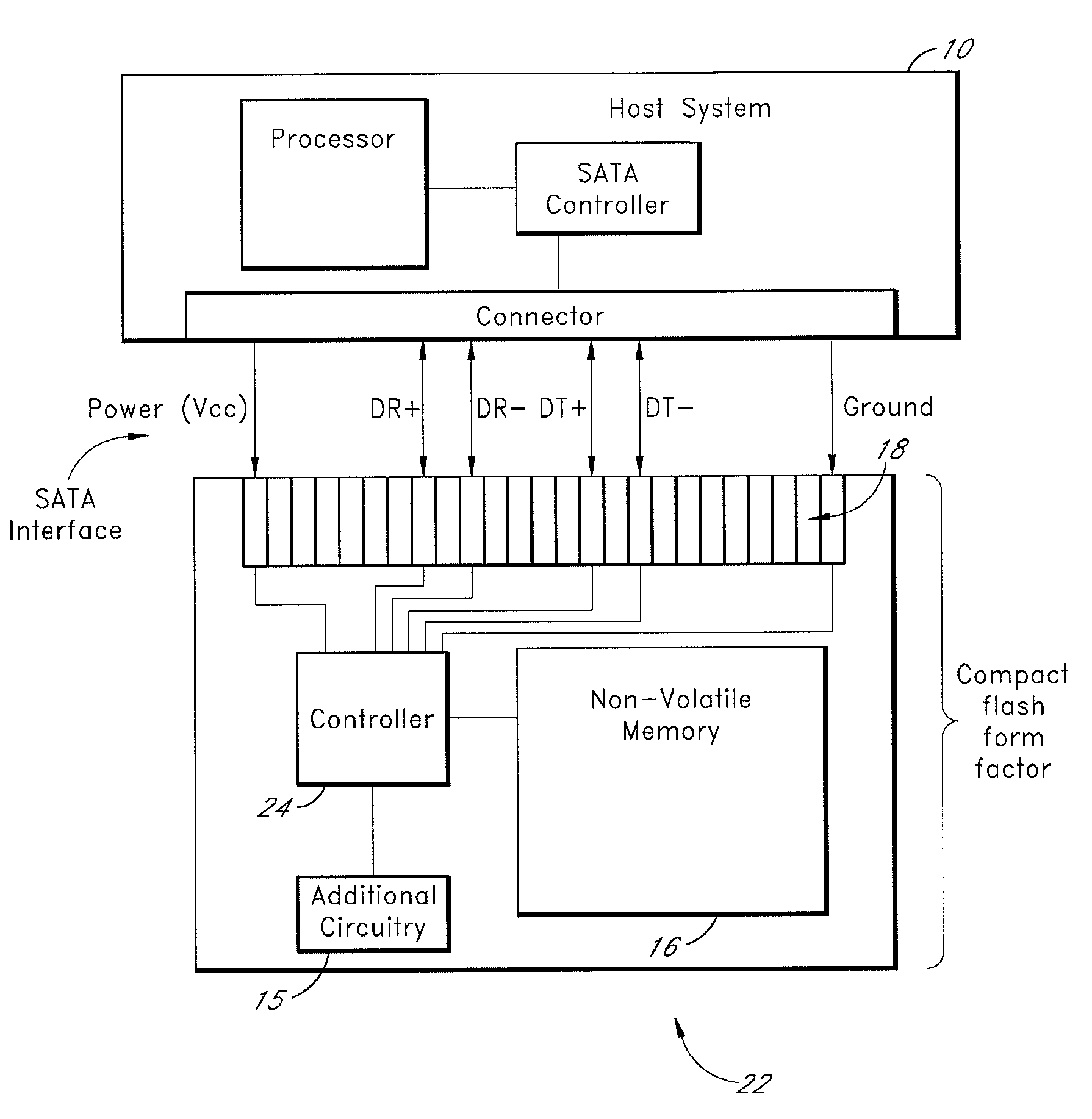
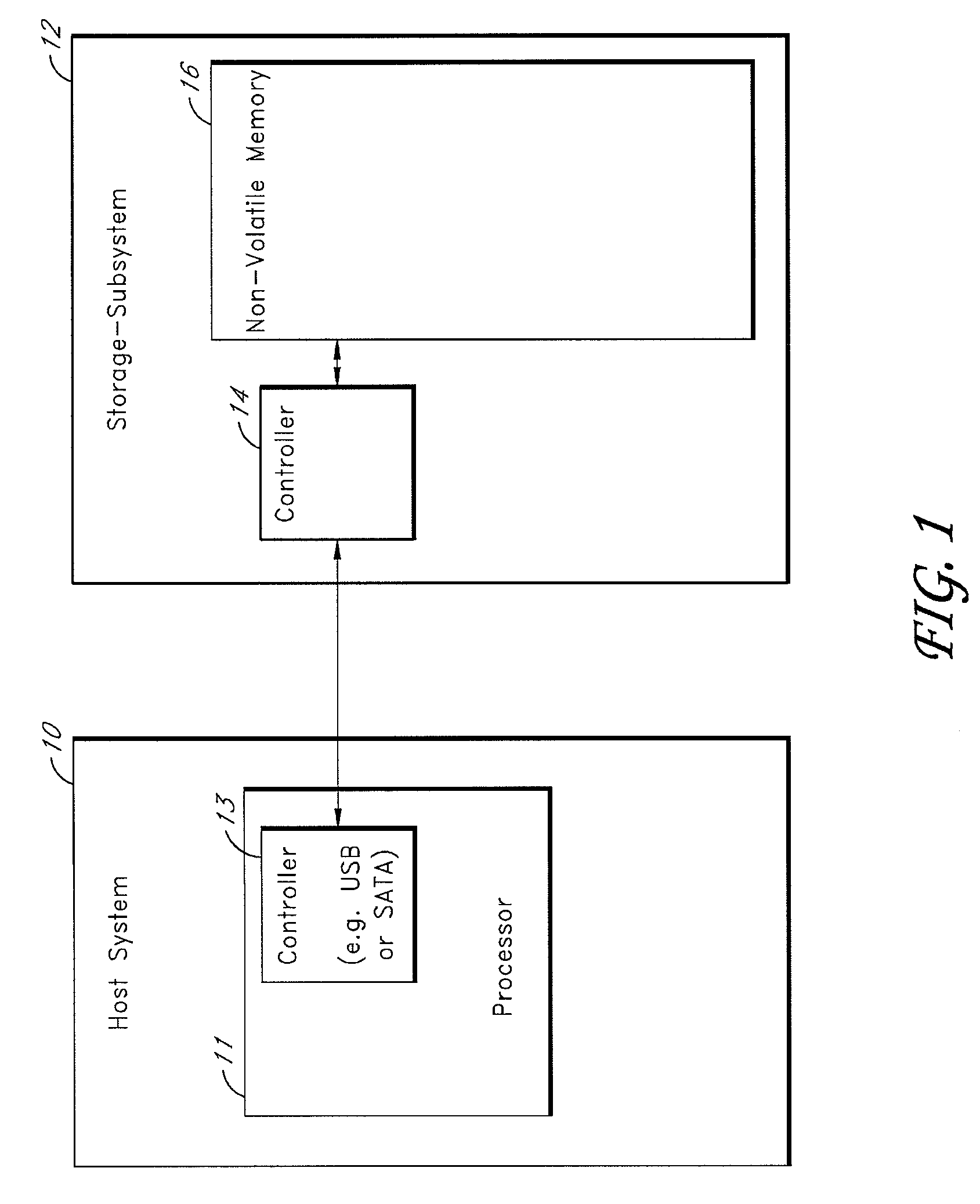
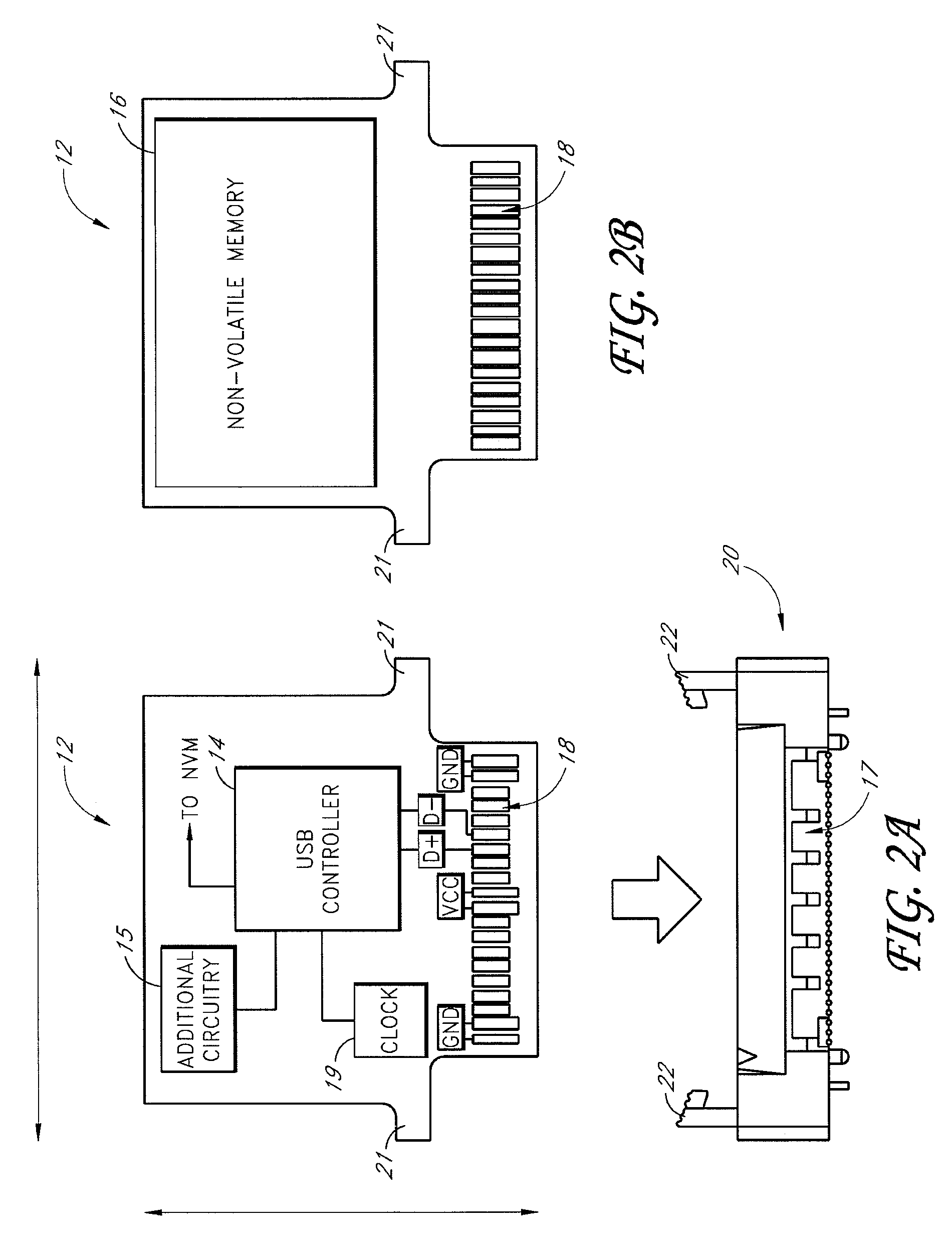
[0007]A non-volatile storage subsystem solution is provided for embedded applications. The storage subsystem is preferably designed to communicate with the host system using a signal interface, such as a USB or SATA (Serial ATA) interface, that uses substantially fewer signal lines than the IDE interface traditionally used for embedded applications. Thus, the amount of board real estate used to carry interface signals in the host system, and the complexity of the board layout in the host system, are significantly reduced. To further reduce board real estate, the host system may, in some embodiments, include a processor that includes an integrated controller (e.g., a USB or SATA controller) corresponding to the host-subsystem signal interface. The use of such a processor eliminates the need for a separate controller device in the host system. The storage subsystem may plug into an internal connector on a circuit board of the host system. The storage subsystem and connector are preferably configured such that the storage subsystem can be selectively locked to the host circuit board, such that a reliable connection is maintained.

Problems solved by technology

The hardware used to implement the IDE interface, however, consumes a significant amount of board real estate within the host system.

Method used


Image

  • Solid state storage subsystem for embedded applications
  • Solid state storage subsystem for embedded applications
  • Solid state storage subsystem for embedded applications

Examples


Embodiment Construction

[0018]Specific embodiments of the invention will now be described with reference to the drawings. This description is intended to illustrate example implementations of, and applications for, the present invention, and is not intended to be limiting. Nothing in this description is intended to imply that any particular feature, characteristic, or mode of operation is a requirement of the invention. The invention is defined by the claims.

[0019]According to specific embodiments of the invention, a storage solution is provided that enables a storage subsystem to easily and cost effectively be embedded in a host system. The host system may be any of a variety of types of computing systems, such as a handheld computer, router, notebook computer, or servers used in industrial, medical or military applications. The host system may be used in an environment, such as plant or control system, in which the host system is commonly subjected to vibration or physical shock. The use of USB storage s...


PUM


Abstract

A non-volatile storage subsystem solution is provided for embedded applications. The storage subsystem is preferably designed to communicate with the host system using a signal interface, such as a USB or SATA interface, that uses substantially fewer signal lines than the IDE interface traditionally used for embedded applications. Thus, the amount of board real estate used to carry interface signals in the host system is reduced. To further reduce board real estate, the host system may include a processor that includes an integrated controller (e.g., a USB or SATA controller) corresponding to the host-subsystem signal interface. The storage subsystem may plug into, and lock to, an internal connector on a circuit board of the host system.

Description

BACKGROUND OF THE INVENTION[0001]1. Technical Field[0002]The present invention relates to solid-state storage subsystems. More specifically, the present invention relates solid-state storage subsystems for embedded applications.[0003]2. Description of the Related Art[0004]Solid-state storage solutions are used to store a wide variety of data. With increasing memory capacity, a mixture of information (e.g., program files, setup files, user data, etc.) can be conveniently stored on a single solid-state storage subsystem such as a removable flash memory card. For some types of storage applications, the storage subsystem is commonly embedded within the host system. For example, an embedded storage subsystem may be used to store boot sequence and operating system code used by the host system.[0005]Storage subsystems used in embedded applications commonly must be capable of tolerating substantial vibration and physical shock without detachment or data loss. The IDE (Integrated Drive Elect...

Claims


Application Information

Patent Timeline
Patent Type & Authority Patents(United States)
IPC IPC(8): G06F13/10G06F12/00
CPCG06F13/385G06F3/0626G06F3/0658G06F3/0688
Inventor MERRY, JR., DAVID E.DIGGS, MARK S.
Owner WESTERN DIGITAL TECH INC
Learn More