
Digital television broadcast signal receiver

a digital television and receiver technology, applied in the field of digital television (iv) broadcast signal receivers, can solve the problems of conventional apparatus, no function for adjusting the direction of the antenna of conventional apparatus, and easy interference of ground wave tv broadcast signal by multi-paths, so as to shorten the time necessary

Inactive Publication Date: 2010-03-23
FUNAI ELECTRIC CO LTD
View PDF19 Cites 23 Cited by
  • Summary
  • Abstract
  • Description
  • Claims
  • Application Information

AI Technical Summary

Benefits of technology

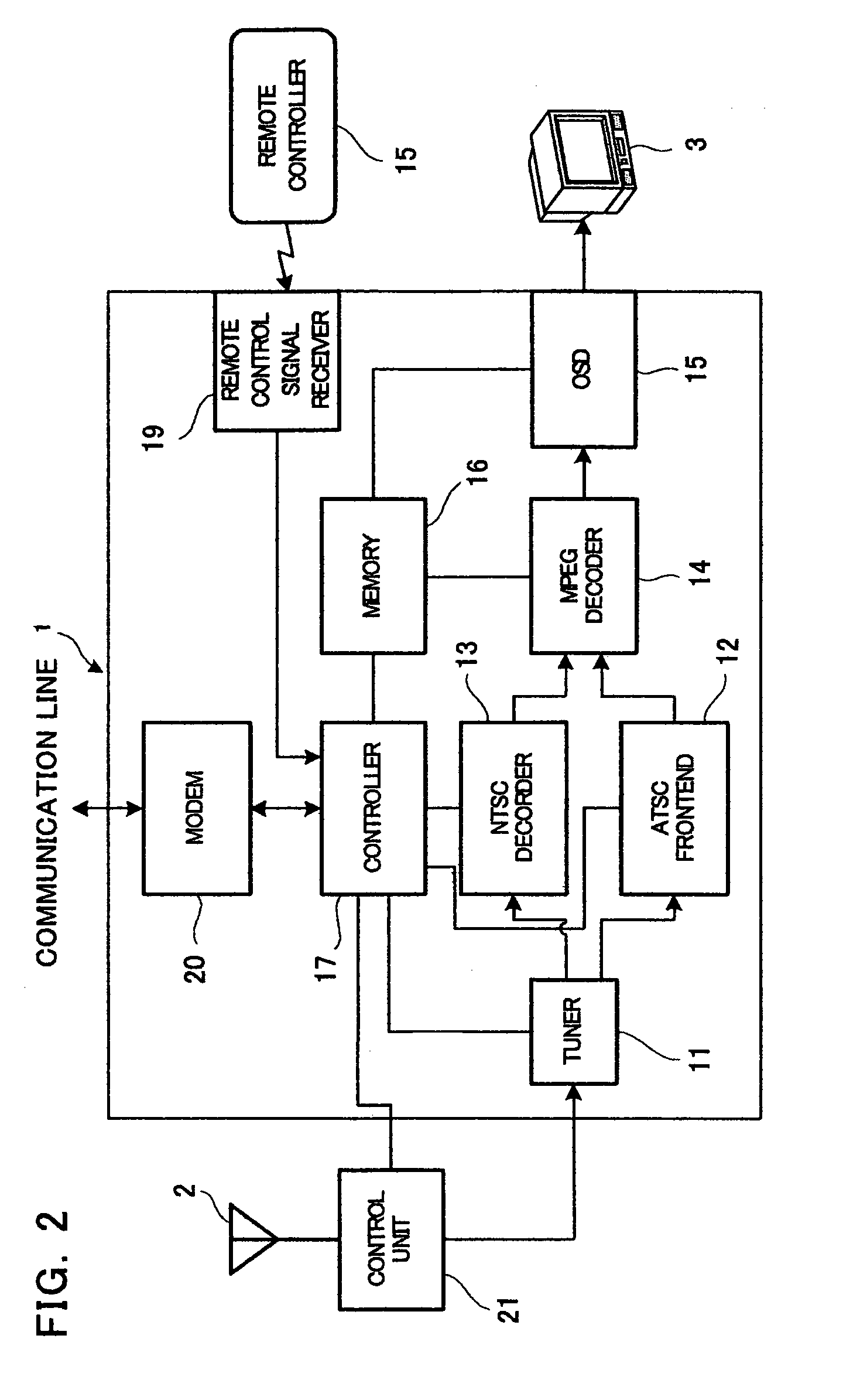
The present invention provides a digital TV broadcast signal receiver that can quickly determine the best signal receiving direction for each channel when using a multi-directional antenna. The receiver includes a tuner, a wireless remote controller, a memory, and a controller. The controller can identify the area and the TV tower that transmits the TV broadcast signals based on the local information and the information of the TV towers. The controller can then decide the optimum signal receiving direction for each channel based on the signal receiving conditions of the TV broadcast signals. This reduces the time needed to determine the optimum signal receiving directions for all the channels. The receiver can also update the information of the TV towers automatically when the channels are altered. Additionally, the receiver can measure the sensitivity of the TV broadcast signals in each signal receiving direction and decide the direction with the highest sensitivity as the optimum signal receiving direction of the channel.

Problems solved by technology

Furthermore, a ground wave TV broadcast signal is easily affected by multi-path due to megastructure.
Such a conventional apparatus, however, has no function for adjusting a direction of an antenna.

Method used


Image

  • Digital television broadcast signal receiver
  • Digital television broadcast signal receiver
  • Digital television broadcast signal receiver

Examples


Embodiment Construction

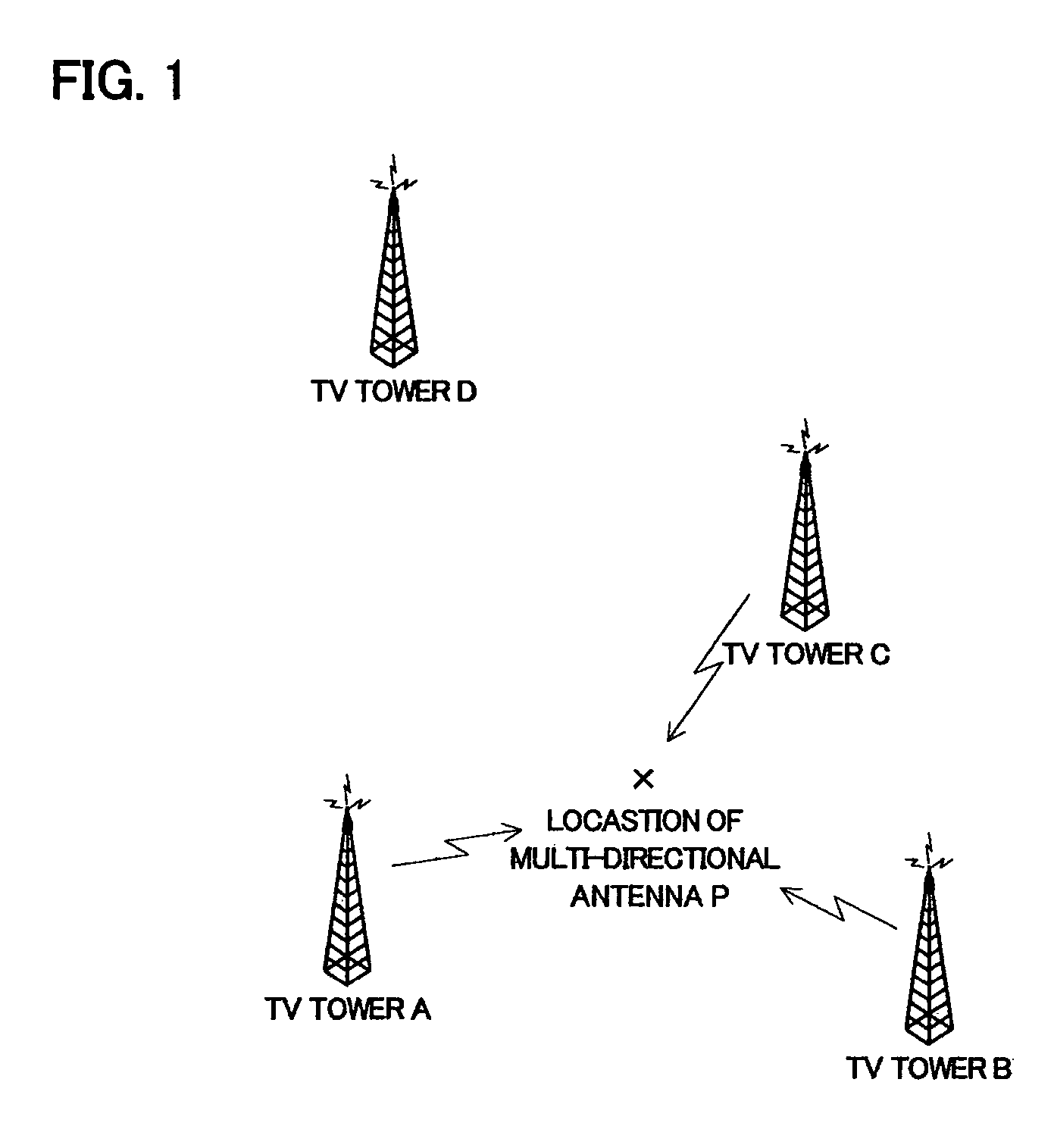
[0024]A digital TV broadcast signal receiver in accordance with an embodiment of the present invention is described with reference to figures. A circumstance for receiving TV broadcast signals in home is shown in FIG. 1. In an area where grand-based digital TV broadcast is performed, when a sensitivity of received signal of a TV broadcast signal is equal to or larger than a predetermined threshold value, an image having a predetermined image quality can be obtained by correction. Thus, it is possible to receive various digital TV broadcast signals transmitted from various TV towers A, B, C, and so on at a location P of a multi-directional antenna, so that TV programs of the receivable channel can be viewed. In correspondence with such a circumstance, a multi-directional antenna having a plurality of signal receiving directions called smart antenna is put into practical use. Besides, it is assumed that a TV tower D in FIG. 1 transmits no digital TV broadcast signal.

[0025]There are va...


PUM


Abstract

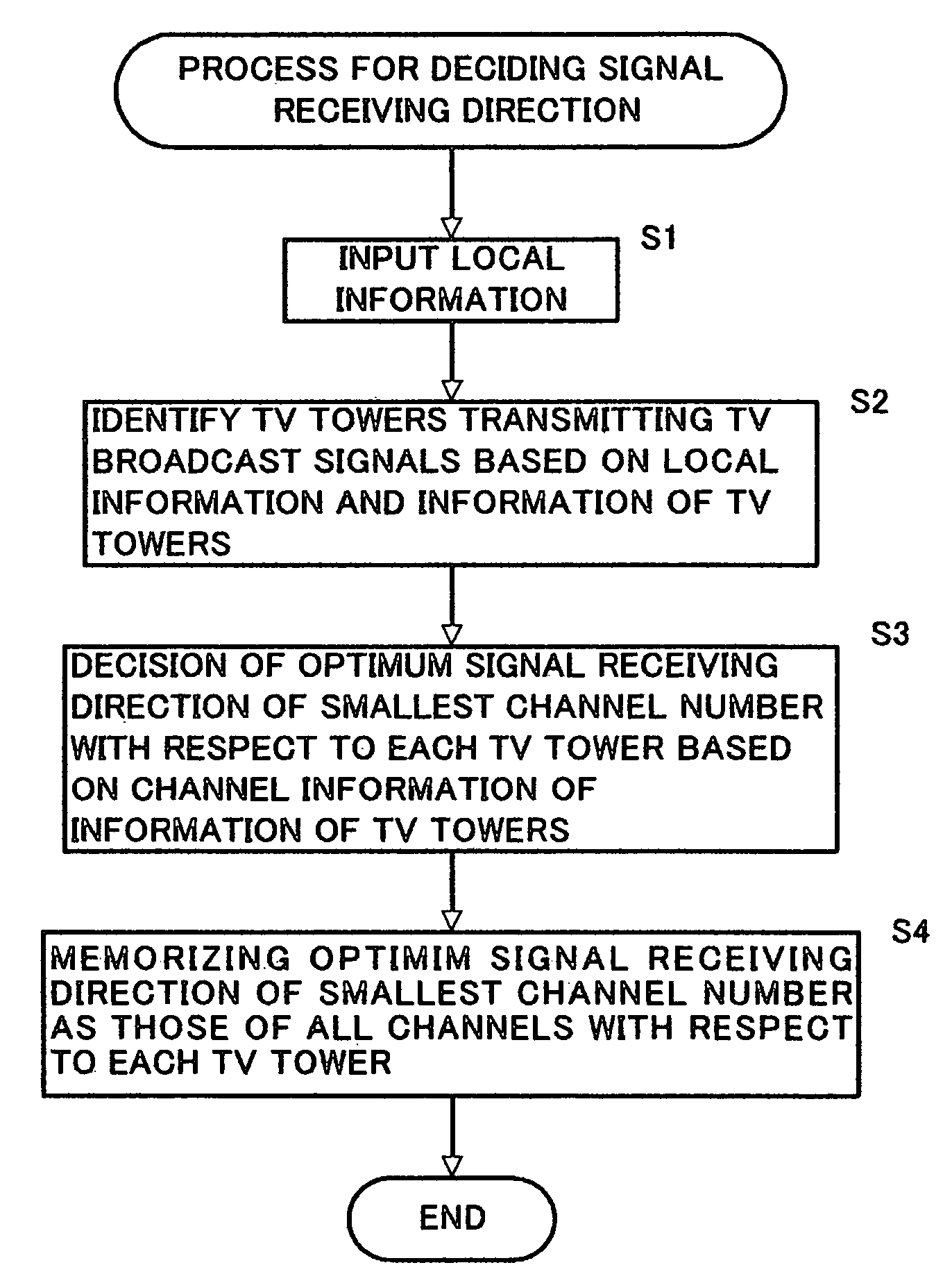
In a digital TV broadcast signal receiver connected to a multi-directional antenna called smart antenna, a time necessary for deciding an optimum signal receiving direction of each receivable channel is shortened with using local information relating to a location of the multi-directional antenna and information of TV towers including location information of TV towers and channel information of channels, TV broadcast signals of which are transmitted from each TV tower. When the local information is inputted, the digital TV broadcast signal receiver identifies at least one TV tower and selects a channel based on the channel information. An optimum signal receiving direction of the selected channel are decided as the optimum signal receiving directions of all the channels transmitted from the same TV tower.

Description

BACKGROUND OF THE INVENTION[0001]1. Field of the Invention[0002]The present invention relates to a digital television (IV) broadcast signal receiver that can receive digital television broadcast signals such as ATSC (Advanced television systems Committee).[0003]2. Description of the Related Art[0004]In the North American Continent where an ATSC digital television broadcast (it is abbreviated to a hereinafter TV broadcast) is performed, plains are dotted with metropolises, so that various TV broadcast signals broadcasted in the suburbs of each metropolis can be received at other cities or the halfway point of the cities. In consideration from a user who receives the TV broadcast signals, since many TV broadcast signals are transmitted in various directions, it is necessary to regulate a direction of an antenna in an orientation to a TV broadcasting station from which a program which he wants to watch is delivered. Therefore, a multi-directional antenna such as a smart antenna is put ...

Claims


Application Information

Patent Timeline
Patent Type & Authority Patents(United States)
IPC IPC(8): H04N7/20H04N5/50H04B1/16H04N5/44H04N11/00
CPCH04N5/4401H04N21/4263H04N21/4622H04N21/435H04N21/44209H04N21/4524H04N21/4345H04N2005/4428H04N21/42222H04N21/426
Inventor MATSUO, MASAHIRO
Owner FUNAI ELECTRIC CO LTD
Learn More