Camera device, camera system and camera calibration method

a technology applied in the field of camera system and camera calibration method, can solve the problems of taking calibration operation, and achieve the effect of reducing the time required for calibration and simplifying the calibration operation of the camera

Active Publication Date: 2013-08-29
KYOCERA CORP +1
View PDF1 Cites 17 Cited by
  • Summary
  • Abstract
  • Description
  • Claims
  • Application Information

AI Technical Summary

Benefits of technology

[0023]According to the embodiments, a calibration operation of the c...

Problems solved by technology

However, there has been a problem that, because of a time lag between an instruction by a user to shift the assumed image and the shift of the assumed im...

Method used


Image

  • Camera device, camera system and camera calibration method
  • Camera device, camera system and camera calibration method
  • Camera device, camera system and camera calibration method

Examples


Embodiment Construction

[0041]Embodiments of the present invention will be described with reference to the accompanying drawings.

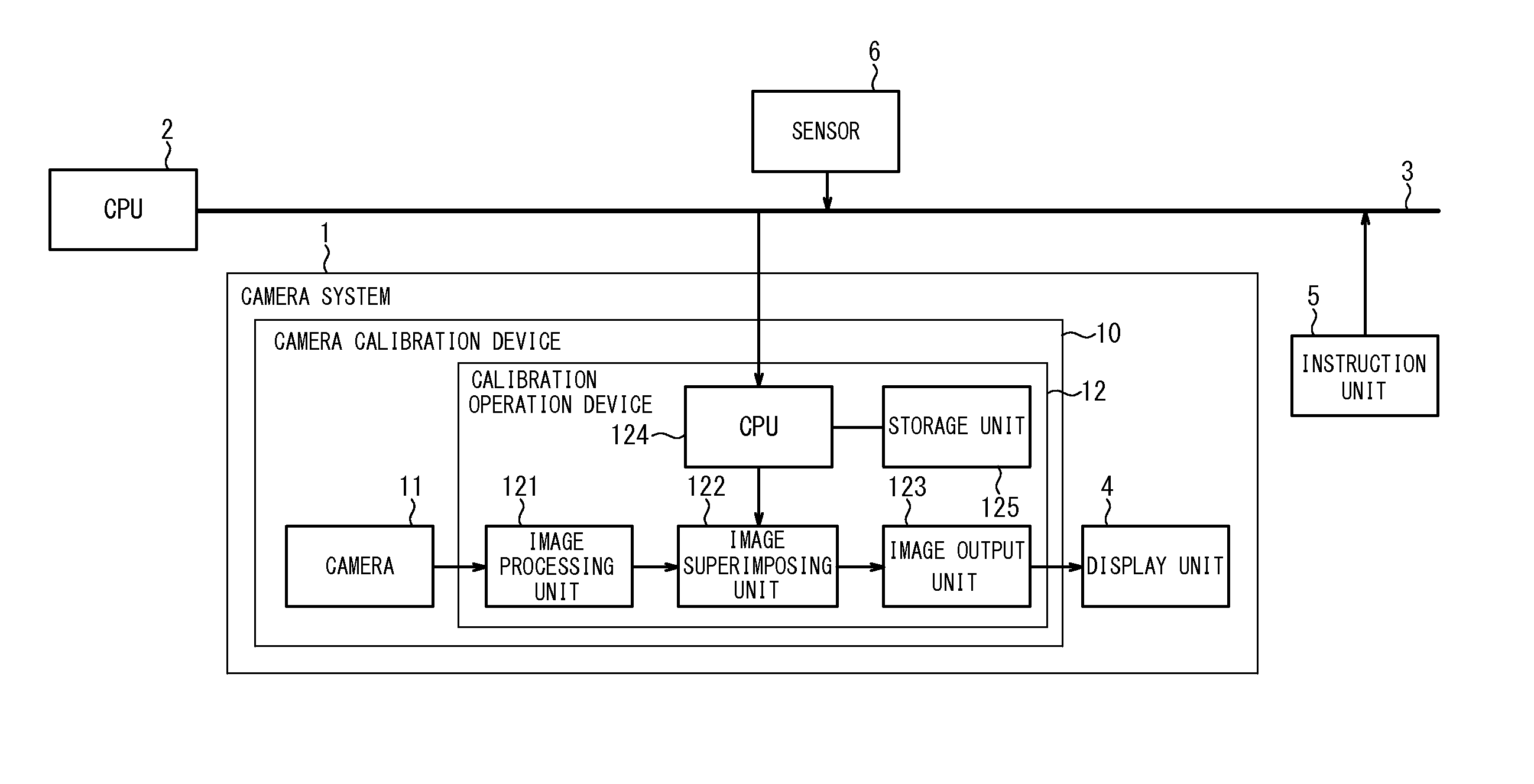
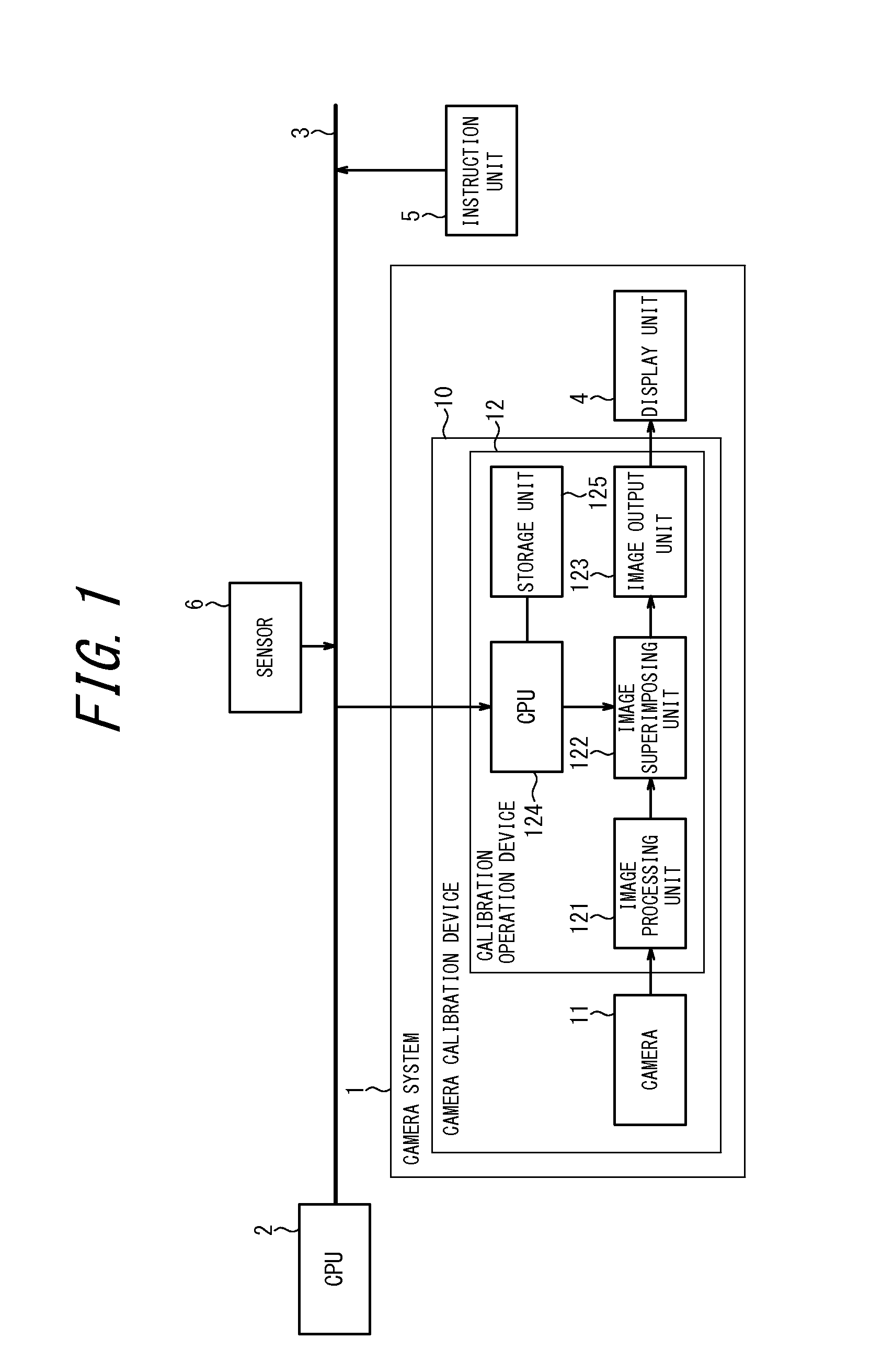
[0042]FIG. 1 is a block diagram illustrating an example of a configuration of a system when a camera system according to the embodiment of the present invention is mounted on a movable object (for example, a vehicle). As illustrate in FIG. 1, the system mounted on the movable object includes a camera system 1, a CPU 2 for controlling the entire system, a bus 3, an instruction unit 5 and a sensor 6. The camera system 1 includes a camera calibration device (camera device) 10 and a display unit 4. The camera calibration device 10 includes a camera 11 and a calibration operation device 12. The calibration operation device 12 includes an image processing unit 121, an image superimposing unit 122, an image output unit 123, a CPU 124 and a storage unit 125.

[0043]The camera 11 has an image sensor such as CMOS or CCD for converting the light of a subject entering through a lens into an el...


PUM


Abstract

An object of the present invention is to simplify a calibration operation of a camera and to shorten a time necessary for calibration. A camera calibration device 10 is mounted on a predetermined position of a movable object 100 and includes a camera 11 configured to take an image including an index 41 provided outside the movable object 100, an image superimposing unit 122 configured to generate a superimposed image by superimposing a calibration object 42 having a position adjustment part and a rotation adjustment part on the image taken by the camera 11, and a calculation unit 124 configured to calculate, based on a position of the calibration object 42 after being shifted in the superimposed image such that an end or a center of the index 41 meets the position adjustment part and a part of the index other than the end or the center overlaps the rotation adjustment part, parameters relative to a pan angle, a tilt angle and a roll angle for calibration of the camera mounting position.

Description

CROSS REFERENCE TO RELATED APPLICATION[0001]This application claims priority to and the benefit of Japanese Patent Application No. 2012-039416 filed on Feb. 24, 2012, the entire contents of which are incorporated herein by reference.FIELD OF THE INVENTION[0002]The present invention relates to a camera device, a camera system and a camera calibration method for calibration of an angle of a camera mounted on a movable object.BACKGROUND OF THE INVENTION[0003]There is known a camera system that enables, by using a camera mounted on a rear side of a vehicle, to display an image behind the vehicle, where it is hard for a driver to view, on a display unit inside the vehicle. For such a system, there is known a method, by adjusting a difference between an assumed image capturing a subject whose position information is known and an actual image of the subject actually taken by the camera, to obtain parameters for calibration of a camera mounting position (for example, see Patent Document 1 a...

Claims


Application Information

Patent Timeline
IPC IPC(8): H04N17/00
CPCH04N17/002G06T7/0018B60R1/00G06T2207/30244G06T2207/10004G06T2207/20092G06T2207/30252G06T7/80
Inventor OSHIMA, TAKEOMAEKAWA, TAKASHISAWADA, RYUUICHIYANAGISAWA, HARUOSAKURAI, CHINATSUIWABUCHI, AKINORITAMIZU, SHINYAINOUE, TAKASHI
Owner KYOCERA CORP
Why Eureka
Try Eureka