Turbo decoding method and turbo decoding apparatus

a decoding method and turbo technology, applied in the direction of code conversion, code conversion, error correction/detection by combining multiple code structures, etc., can solve the problems of increasing delay time and insufficient shortening the time necessary for turbo decoding, so as to shorten the time necessary and shorten the delay time

Inactive Publication Date: 2009-05-05
FUJITSU LTD
View PDF15 Cites 20 Cited by
  • Summary
  • Abstract
  • Description
  • Claims
  • Application Information

AI Technical Summary

Benefits of technology

[0085]Accordingly, an object of the present invention is to make it possible to shorten delay time by shortening the time necessary for turbo decoding through an arrangement that is simple in comparison with the prior-art arrangement.
[0092]In accordance with the present invention as set forth above, memory can be reduced over the prior-art arrangement, the time needed for turbo decoding can be shortened and signal delay due to turbo decoding can be shortened.

Problems solved by technology

Moreover, even if a plurality of turbo decoders are provided, the time necessary for turbo decoding cannot be shortened sufficiently (it is 3.2 ms in the above-described example), and an increase in delay time becomes a problem.

Method used


Image

  • Turbo decoding method and turbo decoding apparatus
  • Turbo decoding method and turbo decoding apparatus
  • Turbo decoding method and turbo decoding apparatus

Examples


first embodiment

(B) First Embodiment

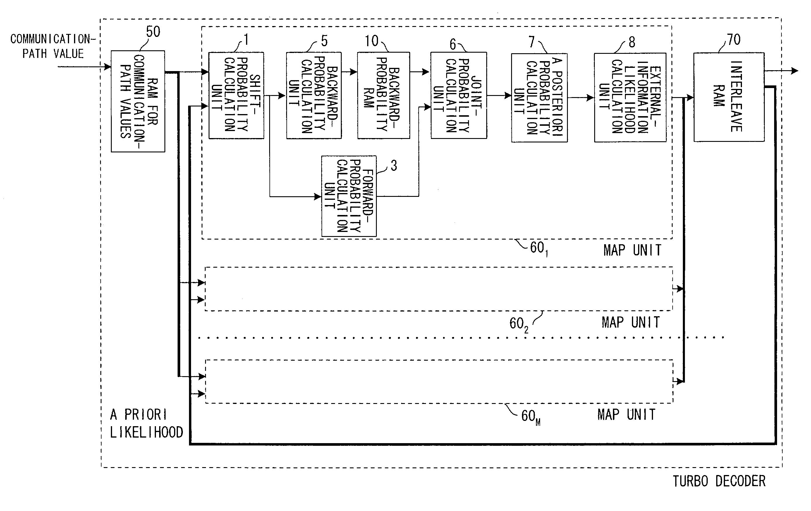
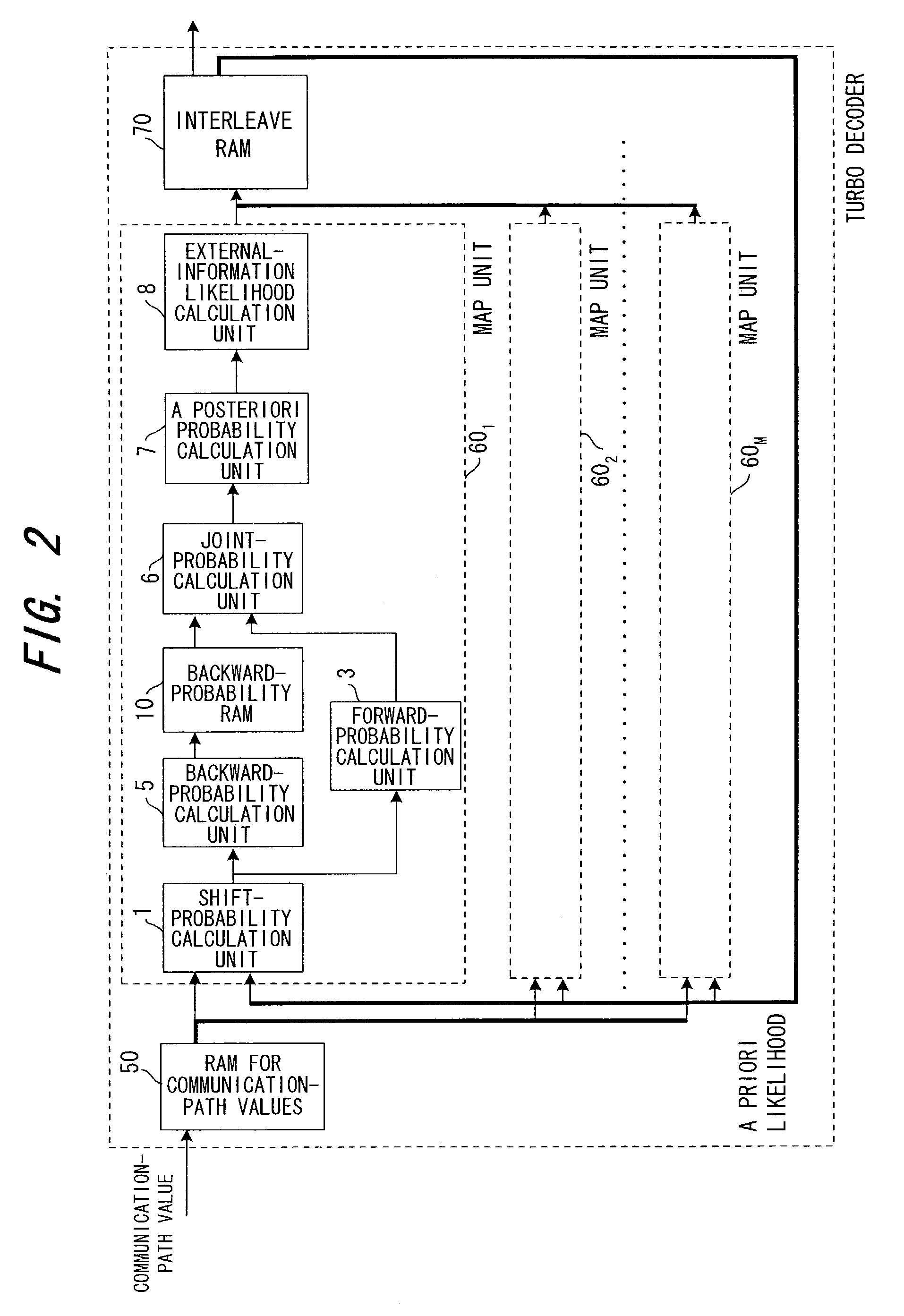
[0143]FIG. 2 is a block diagram of a first embodiment in which data division / simultaneous parallel decoding processing of the present invention is applied to a decoding apparatus (see FIG. 31) that adopts the conventional first MAP decoding method.

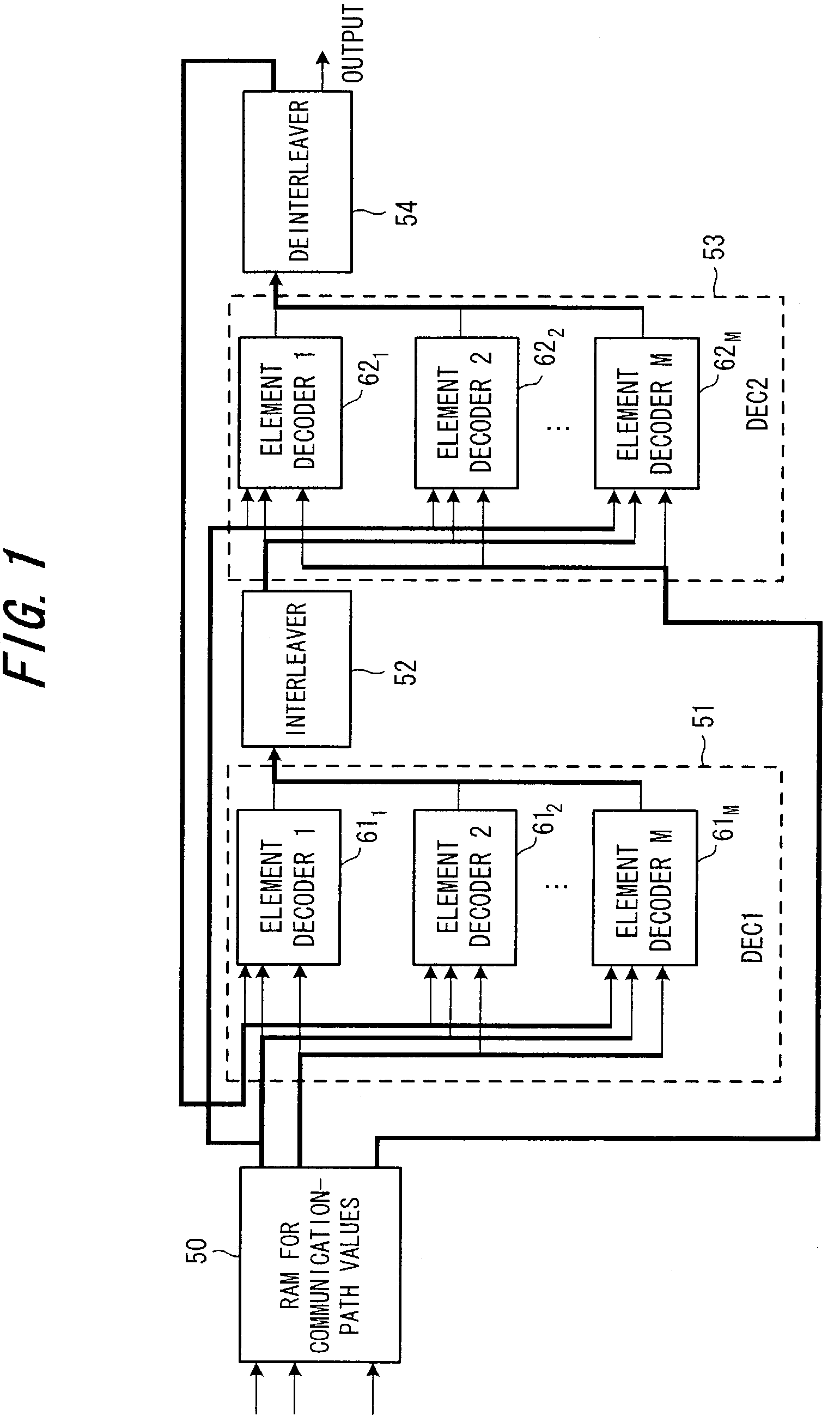
[0144]A MAP unit 601 is used alternately as the first and second element decoders 611, 621 in FIG. 1, namely as an element decoder for the first half of turbo decoding and an element decoder for the second half of turbo decoding, a MAP unit 602 is used alternately as the first and second element decoders 612, 622 in FIG. 1, . . . , and a MAP unit 60M is used alternately as the first and second element decoders 61M, 62M in FIG. 1. An interleave RAM 70 is used alternately as the interleaver 52 and deinterleaver 54 in FIG. 1. The MAP units 601 to 60M are identical in structure and have the shift-probability calculation unit 1, forward-probability calculation unit 3, backward-probability calculation unit 5, RAM 10 for backw...

second embodiment

(C) Second Embodiment

[0165]FIG. 6 is a block diagram of a second embodiment in which data division / simultaneous parallel decoding processing of the present invention is applied to a turbo decoding apparatus that adopts the conventional second MAP decoding method. This arrangement is substantially the same as that of the first embodiment shown in FIG. 2. The difference is that the backward-probability RAM 10 is provided with the continuous-β memory 10a1 and discrete-β memory 10a2.

[0166]FIGS. 7 to 9 are diagrams useful in describing the operation of the second embodiment, and FIG. 10 is a time chart for describing the operation of the second embodiment. In the second embodiment, let signal length obtained by adding tail bits onto information bits be N bits. The RAM 50 for communication-path values divides this signal length into M-number of segments and inputs the divided data to respective ones of the MAP units 601, 602, . . . 60M simultaneously. The MAP units 601, 602, . . . 60M res...

third embodiment

(C) Third Embodiment

[0187]FIG. 11 is a block diagram of a third embodiment in which data division / simultaneous parallel decoding processing of the present invention is applied to a turbo decoding apparatus that adopts the conventional second MAP decoding method. Components identical with those of the first embodiment shown in FIG. 2 are designated by like reference characters. This embodiment differs in that a shared backward-probability RAM 81 and shared forward-probability RAM 82 are provided, backward probabilities calculated from N−1 to 0 and forward probabilities calculated from 0 to N−1 are stored discretely in RAMs 81, 82, respectively, taking time N, and the MAP units 601 to 60M execute MAP decoding processing simultaneously utilizing these backward and forward probabilities.

[0188]FIG. 12 is a diagram useful in describing operation of the third embodiment. The first MAP unit 601 calculates forward probabilities initially from

[0189]N to 0 and stores them discretely in the sha...


PUM


Abstract

Disclosed are a turbo decoding apparatus and method for decoding a turbo-encoded signal by repeating element decoding. The apparatus includes a plurality of element decoders for applying element decoding, e.g., MAP decoding, in parallel to respective ones of a plurality of divided signals to be decoded, and an interleaver / deinterleaver for interleaving or deinterleaving a plurality of results of element decoding collectively. Each element decoder applies element decoding to a respective one of the divided signals, and the interleaver / deinterleaver alternately interleaves and deinterleaves a plurality of results of element decoding collectively. Turbo decoding is carried out by repeating these operations a prescribed number of times.

Description

BACKGROUND OF THE INVENTION[0001]This invention relates to a turbo decoding method and apparatus. More particularly, the invention relates to a turbo decoding method and apparatus for performing turbo decoding at high speed without reducing number of iterations and without causing a decline in encoding gain.[0002]Error correction codes are for the purpose of correcting error contained in received information or in reconstructed information, etc., so that the original information can be decoded correctly. These are applied to a variety of systems. For example, error correction codes are applied in cases where data is to be transmitted without error when performing mobile communication, facsimile or other data communication, or in cases where data is to be reconstructed without error from a large-capacity storage medium such as a magnetic disk or CD.[0003]Among the available error correction codes, turbo code (see the specification of U.S. Pat. No. 5,446,747) recently has become the f...

Claims


Application Information

Patent Timeline
Patent Type & Authority Patents(United States)
IPC IPC(8): H03M13/03H03M13/45H03M13/27H03M13/29H03M13/39H04L1/00
CPCH03M13/2957H03M13/3905H03M13/3927H03M13/3972
Inventor OBUCHII, KAZUHISAYANO, TETSUYA
Owner FUJITSU LTD
Why Eureka
Try Eureka