System and process for base load power generation

a technology of power generation system and process, which is applied in the direction of steam engine plants, climate sustainability, energy industry, etc., can solve the problems of increasing the amount of excess air in the air, lowering the temperature of combustion, and increasing the flow rate of the produced flue gas

Inactive Publication Date: 2010-03-30
KALINA POWER LTD
View PDF21 Cites 32 Cited by
  • Summary
  • Abstract
  • Description
  • Claims
  • Application Information

AI Technical Summary

Problems solved by technology

This excess air results in a lowering of the temperature of combustion.
However, the greater the excess of air, the greater the flow rate of the produced flue gases.
Because the flue gas cannot be cooled to a temperature equal to the initial temperature of the supplied air, the quantity of heat rejected into the atmosphere by the flue gas increases with increasing amounts of excess air.
This results in a reduction of the efficiency of the combustion system.
These systems are, perforce, expensive and complex structures that require a high degree of maintenance, especially due to the fact that the waterwall tubes are subjected to very high thermal stresses.
But in such a case, the temperature in the combustion chamber would become unacceptably high, such that the materials out of which the combustion chamber is constructed would be unable to withstand such temperatures.
Moreover, the flue gases produced would have such a high temperature that they would not be able to be used directly to provide heat to the heat exchangers of a power system, especially if these heat exchangers are used to superheat vapor.
However, even in these cases, the temperature of the flue gas produced is too high to be directly used in the heat exchangers of a power system.
However such an arrangement results in the addition of substantial complications to the entire system.

Method used


Image

  • System and process for base load power generation
  • System and process for base load power generation
  • System and process for base load power generation

Examples


first embodiment

of the System and Method of This Invention

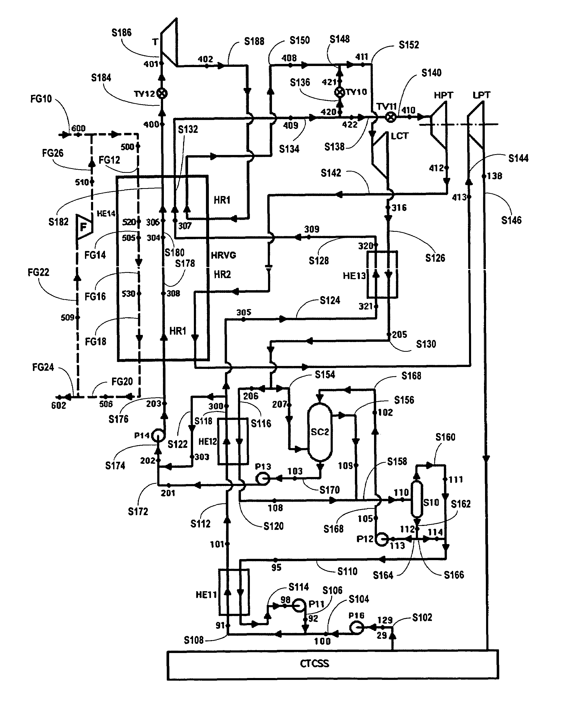
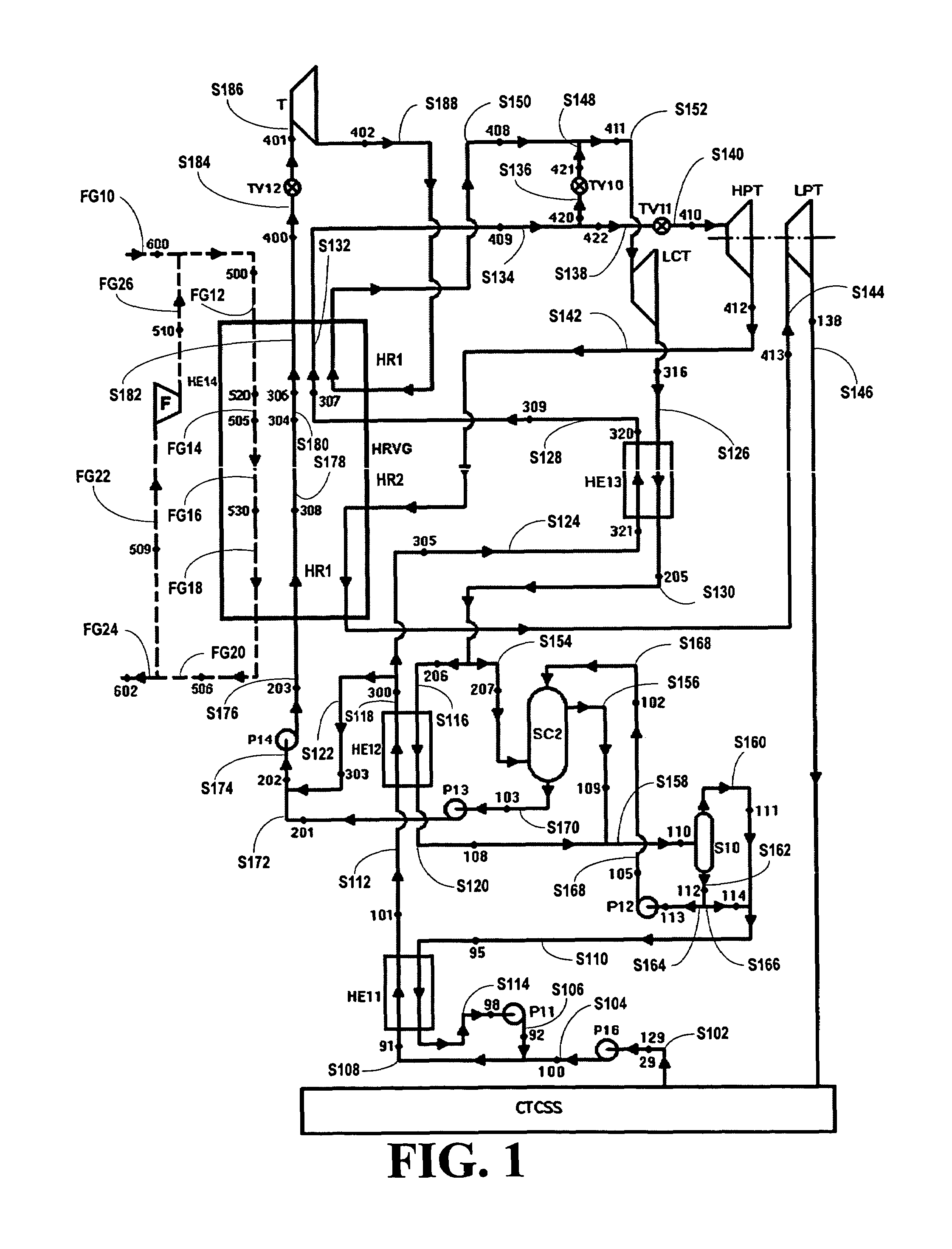
[0038]Referring now to FIG. 1, a schematic block diagram of one embodiment of the system of this inventions, generally 100, is shown. In the system 100, a first fully condensed rich working fluid stream S102 having parameters as at a point 29, where the stream S102 has a high concentration of the low boiling component of the multi-component working fluid, i.e., the stream S102 comprises a rich working fluid stream, exits from a Condensation and Thermal Compression Subsystem CTCSS, where it was fully condensed. The Condensation and Thermal Compression Subsystem CTCSS can be a simple condenser, but is generally a more complex subsystem as described below. The stream S102 having the parameters as at the point 29, redesignated as a point 129, is then pumped by a pump P16, to a desired higher pressure, to form a higher pressure fully condensed rich working fluid stream S104 having parameters as at a point 100. Although the stream S102 having the ...

second embodiment

of the System and Method of This Invention

[0057]Referring now to FIG. 3, an alternate embodiment of the system of this invention, generally 300, is shown. Although this is a second embodiment, the point and stream designations used in the first embodiment of FIG. 1 are used, when appropriate, in the description of this system 300. In the system 300, a first fully condensed rich working fluid stream S102 having parameters as at a point 29, where the stream S102 has a high concentration of a low boiling component of the multi-component working fluid, exits a Condensation and Thermal Compression Subsystem CTCSS, where it was fully condensed. The Condensation and Thermal Compression Subsystem CTCSS can be a simple condenser, but is generally a more complex subsystem as described below. The stream S102 having the parameters as at the point 29, redesignated as a point 129, is then pumped by a first pump P16, to a desired higher pressure, to form a first higher pressure rich working fluid ...


PUM


Abstract

A system and process are disclosed for converting thermal energy into power from three different compositional streams of a multi-component working fluid, one of the streams being a lean working fluid stream pressurized into its super-critical state before being vaporized in a heat recovery vapor generator, another stream is a rich working fluid steam and the third stream is an intermediate working fluid stream, where the system and process has increased overall efficiency.

Description

BACKGROUND OF THE INVENTION[0001]1. Field of the Invention[0002]The present invention relates to a system and process for the generation of electrical power or other useable energy in base load applications by converting thermal energy in working fluid stream into the power or other useable energy.[0003]More particularly, the present invention relates to a system and process for the generation of electrical power or other useable energy in base load applications, the system and process involves converting thermal energy into electrical power or other useable energy from three different compositional streams of a multi-component working fluid, one of the streams being a lean working fluid stream pressurized into its super-critical state before being vaporized in a heat recovery vapor generator, another stream is a rich working fluid steam and the third stream is an intermediate working fluid stream, where the system and process of this invention has increased overall efficiency.[0004...

Claims


Application Information

Patent Timeline
Patent Type & Authority Patents(United States)
IPC IPC(8): F01K25/06
CPCF01K7/32F01K25/065Y02P80/15
Inventor KALINA, ALEXANDER I.
Owner KALINA POWER LTD
Why Eureka
Try Eureka