Device for movable support of an input/output unit

a technology for movable support and input/output unit, which is applied in the direction of passenger space, monocoque construction, portable lifting, etc., and can solve the problem of large installation spa

Inactive Publication Date: 2010-03-30
FISCHER AUTOMOTIVE SYST
View PDF18 Cites 25 Cited by
  • Summary
  • Abstract
  • Description
  • Claims
  • Application Information

AI Technical Summary

Benefits of technology

[0008]The device according to the invention comprises a coupling element, which synchronises the movement of the input / output unit and the movement of the cover. The coupling element is driven by the drive of the input / output unit and in turn drives the gear mechanism of the cover. Synchronisation is to be understood to mean a co-ordination of the movements of the cover and of the input / output unit that prevents collision of the cover and the input / output unit during opening and setting up into the position of use respectively and during the reverse movements of the cover and the input / output unit. Synchronisation means, although not necessarily so, a simultaneous movement of the cover and the input / output unit or a movement with a speed ratio that is always constant. In phases of the movements, the cover or input / output unit can be slower or faster than in other phase of the movement, and the cover and / or input / output unit can also be stationary during phases of the movements.
[0009]The coupling element facilitates the drive of the input / output unit and of the cover using a common drive. A further advantage of the coupling element is the synchronisation of the movements of the input / output unit and of the cover and the prevention of a collision of the two parts.
[0010]The coupling element can be, for example, a cam plate or similar. In one construction according to the invention the coupling element is pivotally mounted. It is, for example, pivotally mounted in a fixed position on a lateral wall of a housing of the device. One construction according to the invention provides for the coupling element to have a curve, which is followed by the drive as the input / output unit is pivoted, the drive moving the coupling element, which in turn activates the gear mechanism of the cover. The curve can be, for example, a cranked track and the coupling element can be a cam plate or slotted plate. The shaping of the curve allows the input / output unit and the cover to be synchronised in the desired manner and the ratio of the speeds of the movements of the input / output unit and the cover to be altered in the desired manner during pivoting of the input / output unit.
[0011]One construction according to the invention provides intermeshing toothings of the coupling element and the gear mechanism of the cover for driving the gear mechanism, and hence the cover, by the coupling element. The toothings can be circular in the manner of gearwheels or alternatively in the form of a gearwheel meshing with a toothed rack. At least one of the two intermeshing toothings can be straight or be formed with a curvature other than circular, that is, with a curved course. The toothings have the advantage that they ensure the synchronous running of the coupling element and the cover; the position of the coupling element determines the position of the cover explicitly.
[0013]One construction according to the invention provides a four-bar linkage as gear mechanism and guidance for the cover of the device. If the four-bar linkage is in the form of a parallelogram, during opening and closing the cover is displaced parallel on a circular arc-shaped path. If the linkage is other than a four-bar linkage, in addition to its translatory motion the cover can be pivoted on a circular arc-shaped path. With a four-bar linkage, a low-priced, stable and reliable guidance of the cover is possible in a simple manner. The geometry of the four-bar linkage allows a desired movement of the cover to be achieved.

Problems solved by technology

The known device requires a large installation space for the pivoting movements of the screen and the cover.

Method used


Image

  • Device for movable support of an input/output unit
  • Device for movable support of an input/output unit
  • Device for movable support of an input/output unit

Examples


Embodiment Construction

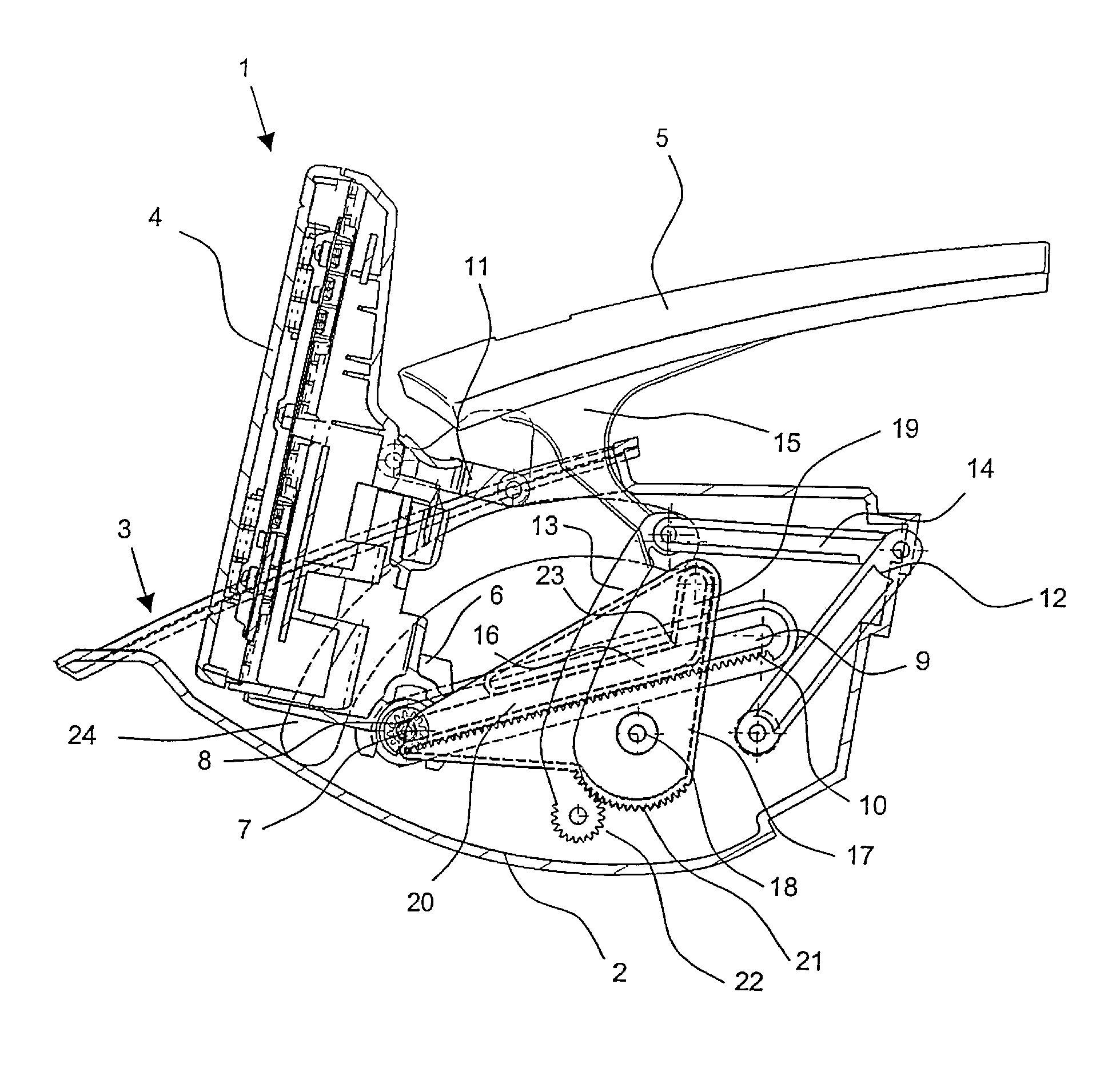
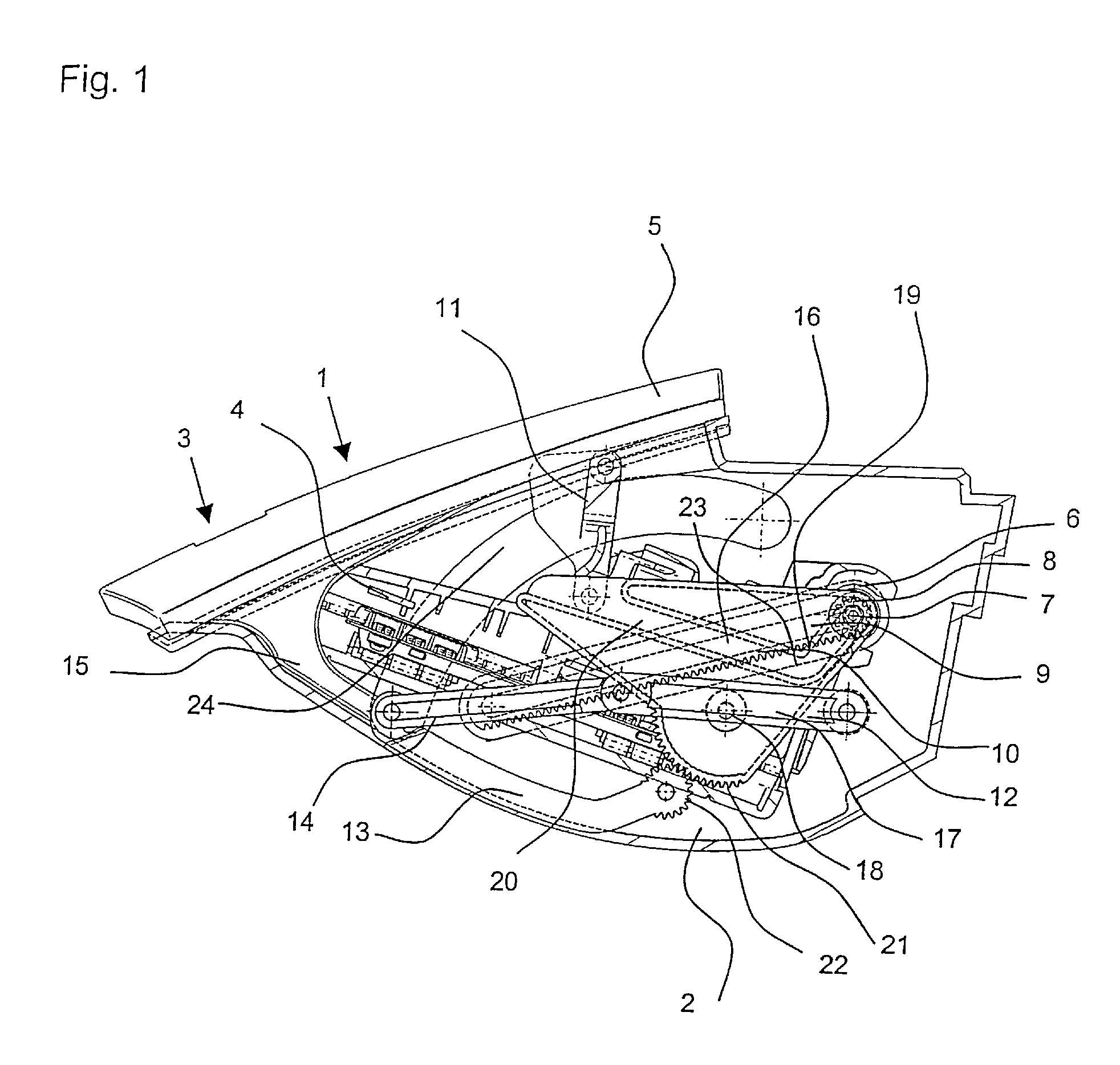
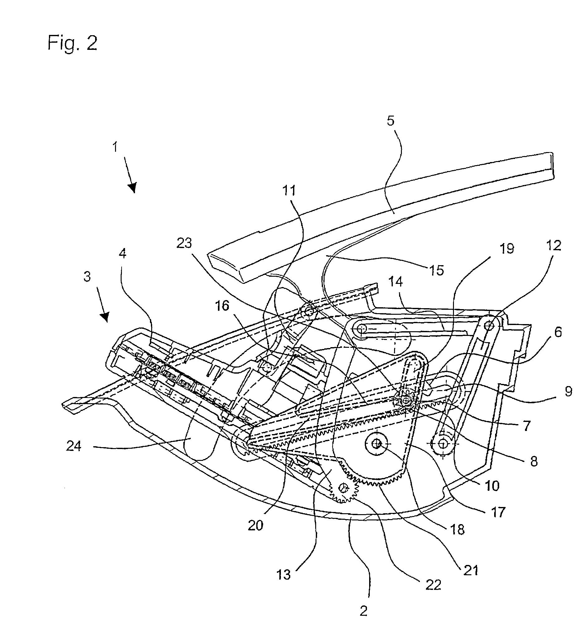
[0016]The device 1 according to the invention illustrated in the drawings comprises a box-form housing 2 having an opening 3, which in a planned installation position is situated at a top face of the housing 2 and occupies more than half of the top face of the housing 2. The device 1 is intended for installation in a dashboard (not shown) of a motor vehicle. The housing 2 is shown transparent, to render built-in parts visible. A screen 4, for example an LCD flat screen, which forms an output unit and is intended as multi-function display for driver information, is housed in the housing 2. In principle, the screen 4 can also have keys and other operating elements, or can be what is known as a touch screen, and hence form an input / output unit. In a closed position illustrated in FIG. 1, the screen 4 is let in flush in the housing 2 in a lying position, with its viewing side directed downwards. A cover 5 closes off the opening 3 of the housing 2. In an opened position illustrated in FI...


PUM


Abstract

A device for movable support for an input / output unit, especially a flat screen, which is electromotively pivotable from a lying non-use position into an upright position of use and vice versa and which in the non-use position is covered by a cover. The movement of the cover is coupled with the movement of the input / output unit by means of a cam plate as coupling element.

Description

TECHNICAL FIELD OF THE INVENTION[0001]The invention relates to a device for movable support of an input / output unit.[0002]The invention is intended in particular for installation and use in motor vehicles, and is basically suitable for use in other land, air or water vehicles as well. The input / output unit under consideration is in particular a flat screen or a display. The input / output unit can also have keys or other input elements.[0003]The input / output unit of the device according to the invention is pivotable about in particular a horizontal axis out of a lying non-use position into an upright position of use and vice versa, the terms “lying” and “upright” relating to a planned installation position of the device. In its upright position of use, the input / output unit is visible to and can be read by or operated by the occupants of the vehicle. In its non-use position, the input / output unit is let in flush, for example, in a kind of housing in a dashboard. Pivoting of the input / ...

Claims


Application Information

Patent Timeline
Patent Type & Authority Patents(United States)
IPC IPC(8): F16H55/17
CPCB60R11/02B60R2011/0005B60R2011/0082Y10T74/1987B60R2011/0092B60R2011/0094B60R2011/0084
Inventor LEOPOLD, GUNTERSTERN, ARMIN
Owner FISCHER AUTOMOTIVE SYST
Why Eureka
Try Eureka