
Vehicle steering systems

a steering system and vehicle technology, applied in the direction of electrical steering, fluid steering, transportation and packaging, etc., can solve the problems of expensive proprietary power steering units and relatively little steering feedback provided to the driver

Active Publication Date: 2010-03-30
AGCO SA (FR)
View PDF28 Cites 6 Cited by
  • Summary
  • Abstract
  • Description
  • Claims
  • Application Information

AI Technical Summary

Benefits of technology

[0021]Preferably, each connection also includes a locking valve controlled by the control unit which locks the flow of fluid from the hydraulic motor down the connection to prevent the turning of the associated steering wheel in the direction which generates the locked flow when the steering actuator reaches a predetermined end position or encounters a temporary obstruction to turning.
[0022]Preferably also the steering actuator control valve means is a three position valve which has a closed position, a left turn position and a right turn position, the three position valve being biased to its closed position and being moveable to its left and right turn positions in response to electrical signals received from the control unit. Such an arrangement is particularly advantageous as it avoids the need to use a relatively expensive power steering unit.
[0023]The steering system may also include a shock protection valve means which limits the maximum level of pressure which can be generated in the steering circuit.

Problems solved by technology

One of the problems of such systems is that the system provides relatively little steering feedback to the driver and this is particularly disadvantageous when the vehicle is being driven at higher speeds.
Also such systems often use expensive proprietary power steering units.

Method used


Image

  • Vehicle steering systems
  • Vehicle steering systems
  • Vehicle steering systems

Examples


Embodiment Construction

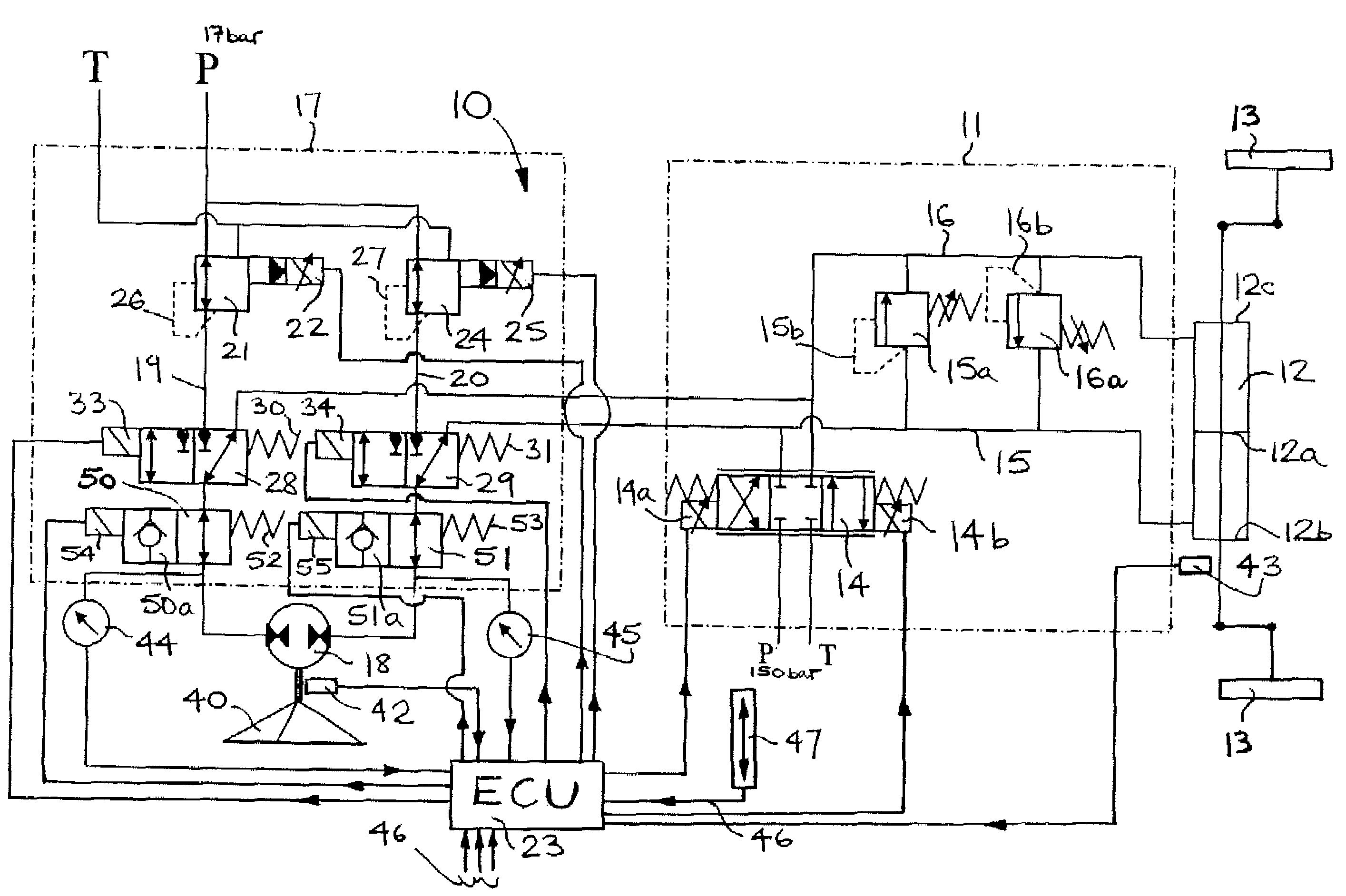
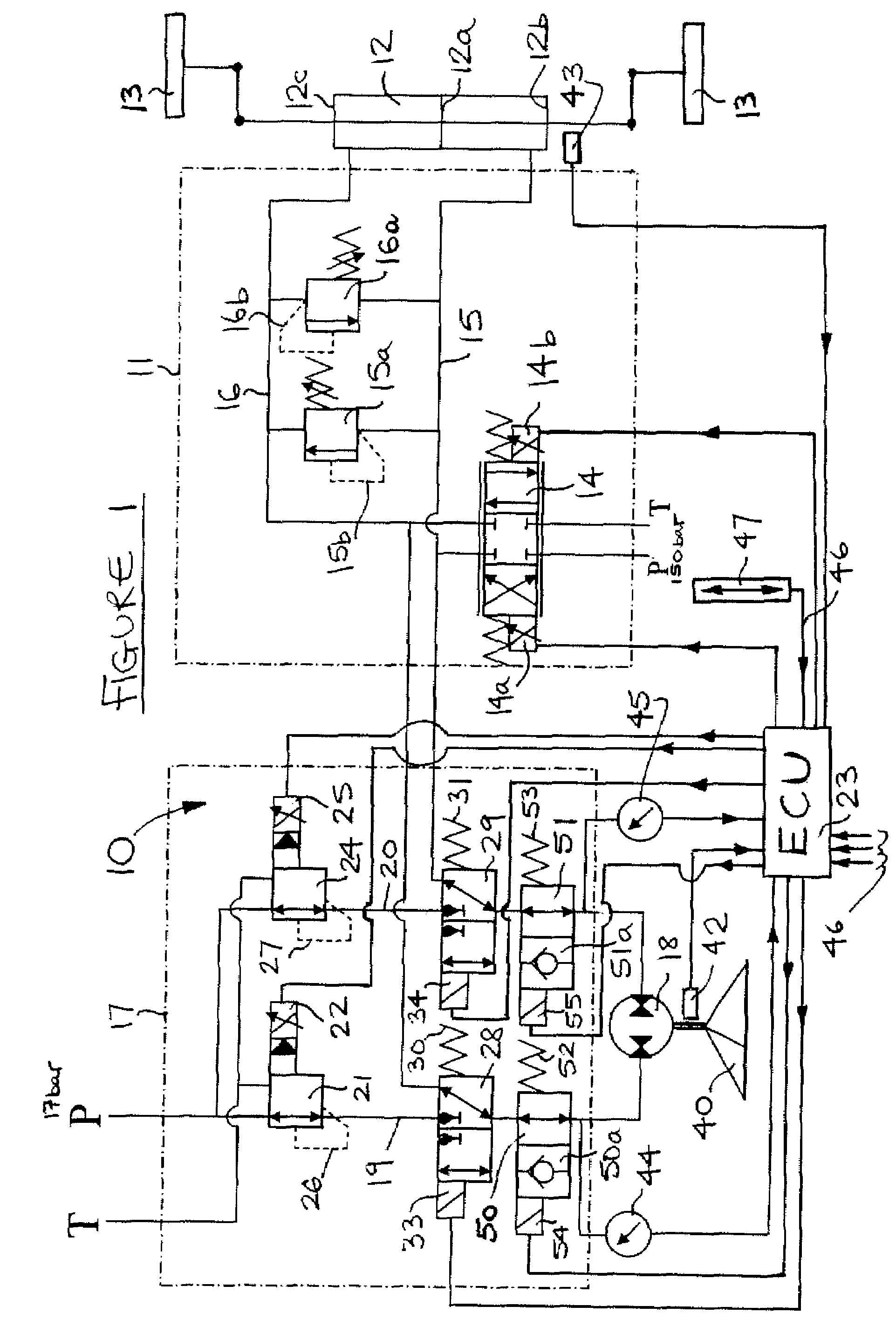
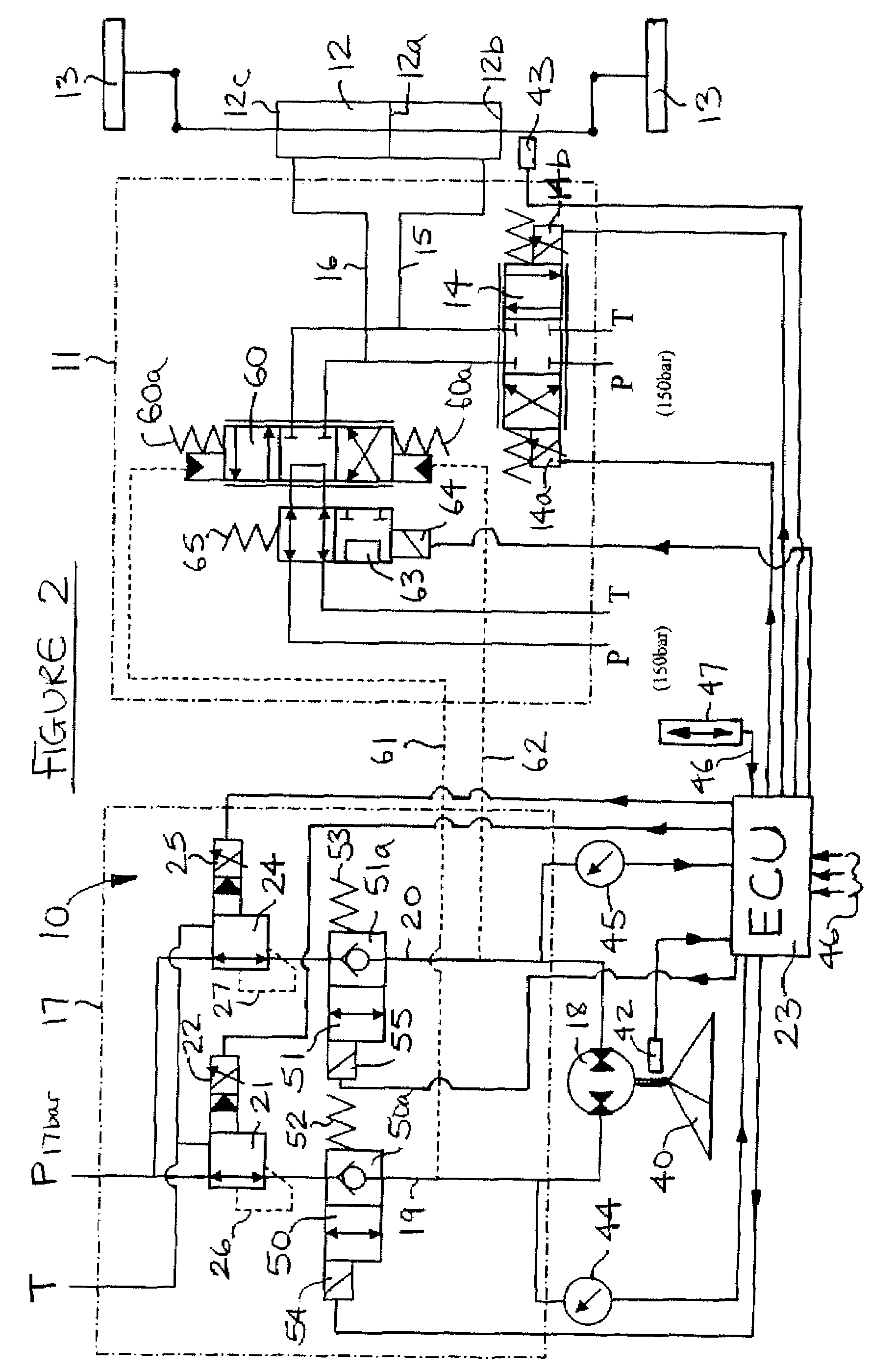
[0027]Referring to the drawings, a steering system 10 for use in a tractor or similar utility vehicle has a steering circuit 11 which includes a steering actuator 12 connected to a pair of steerable wheels 13 and three position steering valve 14 which supplies pressurized fluid to the right and left hand turn lines 15 and 16 of the circuit from a source of pressurized fluid P which has a tank return line T.

[0028]Steering valve 14 is controlled by an electronic control unit 23 which receives signals from a sensor 42 associated with a steering wheel 40 and from a sensor 43 associated with actuator 12 which measures the current turn angle of wheels 13. Control unit 23 issues control signals to the solenoids 14a and 14b of steering valve 14 to control the supply of fluid to actuator 12 to turn wheels 13 to the desired turn angle set by the driver using steering wheel 40. The steering circuit also includes shock protection valves 15a and 16a, associated with lines 15 and 16 respectively,...


PUM


Abstract

A vehicle steer by wire system which has a steering wheel for setting a desired turn angle of a vehicle wheel, a steering wheel turn sensor for sensing the desired turn angle, a hydraulic steering actuator for turning the wheel, a wheel turn sensor for sensing the current wheel turn angle and a control unit for receiving the desired turn angle and current wheel turn angle signals. An electronically controlled steering actuator control valve means is provided for supplying pressurized fluid to the steering actuator via a steering circuit in response to signals from the control unit to turn the wheel to the desired turn angle. A hydraulic motor connected with the steering wheel is provided to provide steering feedback to the steering wheel via a feedback circuit which includes an electrically controlled hydraulic feedback control valve means which directs fluid to and from the hydraulic motor in response to the signals from the control unit to generate the steering feedback. The steering system has a fail-safe mode in which fluid pressure from the hydraulic motor provides steering of the wheel in the event of a failure to electronically actuate the steering actuator control valve means.

Description

BENEFIT CLAIM[0001]This application is based on, and claims the benefit of priority to, UK application GB 0617052.6, filed 30 Aug. 2006, which priority application is hereby incorporated by reference.BACKGROUND OF THE INVENTION[0002]1. Field of the Invention[0003]This invention relates to vehicle steering systems, and in particular to such systems which are suitable for use on a tractor or similar utility vehicle.[0004]2. Description of Related Art[0005]It is well known in such vehicles to steer the vehicle using a hydraulically operated steering actuator which is supplied with pressurized fluid from a pressurized source to provide power assisted steering. One of the problems of such systems is that the system provides relatively little steering feedback to the driver and this is particularly disadvantageous when the vehicle is being driven at higher speeds. Also such systems often use expensive proprietary power steering units.[0006]It is an object of the present invention to provi...

Claims


Application Information

Patent Timeline
Patent Type & Authority Patents(United States)
IPC IPC(8): B62D5/06
CPCB62D3/14B62D5/001B62D5/003B62D5/006B62D5/091B62D5/30B62D6/008
Inventor HUBLART, BERNARDDEMAN, CEDRICSHUTE, MALCOLMCHAUVEL, VINCE
Owner AGCO SA (FR)
Learn More