Sheet stacking device and image forming apparatus including the same

a stacking device and stacking technology, applied in the direction of pile receivers, thin material handling, transportation and packaging, etc., can solve the problems of difficult to uniformly obtain good stacking performance of sheets of all sizes, and affecting the smooth ejecting of sheets. , to achieve the effect of simple structure, good stacking performance and simple structur

Inactive Publication Date: 2010-03-30
SHARP KK
View PDF19 Cites 16 Cited by
  • Summary
  • Abstract
  • Description
  • Claims
  • Application Information

AI Technical Summary

Benefits of technology

[0012]It is an object of the present invention to provide a sheet stacking device that can obtain a good stacking performance with a simple structure and that can be applied to an apparatus that includes a plurality of sheet stacking sections. A sheet presser arm according to the present invention has a simple structure capable of being applied to the apparatus such as a movable job separator that includes a plurality of sheet stacking sections. Further, according to the present invention, tray-full prediction or tray-full detection can be performed with a simple configuration.
[0013]According to a first aspect of the present invention, there is provided a sheet stacking device comprising: an evacuation section for transporting and ejecting sheets; a sheet exit tray for stacking the ejected sheets; an arm supporting member; and a sheet presser arm including a supported end at one end, a free end at the other end which is capable of pressing the sheets stacked on the sheet exit tray directly or via a contact member attached to the free end, and a flexure portion having flexibility between the supported end and the free end, the supported end being attached to the arm supporting member, wherein the arm can apply, by the flexibility of the flexure portion, a pressing force to the sheets stacked on the sheet exit tray and a repulsive force to each of the ejected sheets when a front end of the ejected sheet strikes against the arm.
[0014]According to a second aspect of the present invention, there is provided a sheet stacking device comprising: an evacuation section for transporting and ejecting sheets; a sheet exit tray for stacking the ejected sheets; an arm supporting member located above the evacuation section; and a sheet presser arm including a supported end at one end, a free end at the other end which is capable of pressing the sheets stacked on the sheet exit tray directly or via a contact member attached to the free end, and a flexure portion having flexibility between the supported end and the free end, the flexure portion having a bend or a curve, the supported end being attached to the arm supporting member; a flexure restricting section located above the arm for restricting an upward movement of the flexure portion which moves upward while flexing as the free end rises; a tray-full prediction sensor for detecting that the upward movement of the flexure portion is restricted by the flexure restricting section; and a tray-full detection sensor for detecting, when the free end still rises even after the upward movement of the flexure portion is restricted, that the limit of the upward movement of the free end is reached.

Problems solved by technology

Actually, however, it is difficult to uniformly obtain the good stacking performance for the sheets of all sizes.
It is difficult to obtain a uniform action of the sheet presser arm.
In this case, if the sheet of a large size is insufficiently stiff or a force of the arm that presses the sheet is excessively strong, then the sheet is wrinkled or smooth eject of the sheet is hampered and the forward movement of the front end of the sheet is often stopped.
Furthermore, there is a limit to the number of stackable sheets whether the number is small or large.
A mechanism of such a sheet presser arm tends to be complicated.
However, if sheets of a large size are stacked, a contact area between upper and lower sheets is large in stacked states and a frictional force that acts on the sheets is high.
In order to secure the sharp gradient, excessive spaces are necessary below and above the tray, which is disadvantageously unsuited for a small-sized sheet tracker.

Method used


Image

  • Sheet stacking device and image forming apparatus including the same
  • Sheet stacking device and image forming apparatus including the same
  • Sheet stacking device and image forming apparatus including the same

Examples


first embodiment

[0079]In a first embodiment, an overall structure of a sheet stacking device and that of an image forming apparatus that includes the sheet stacking device according to the present invention will be described.

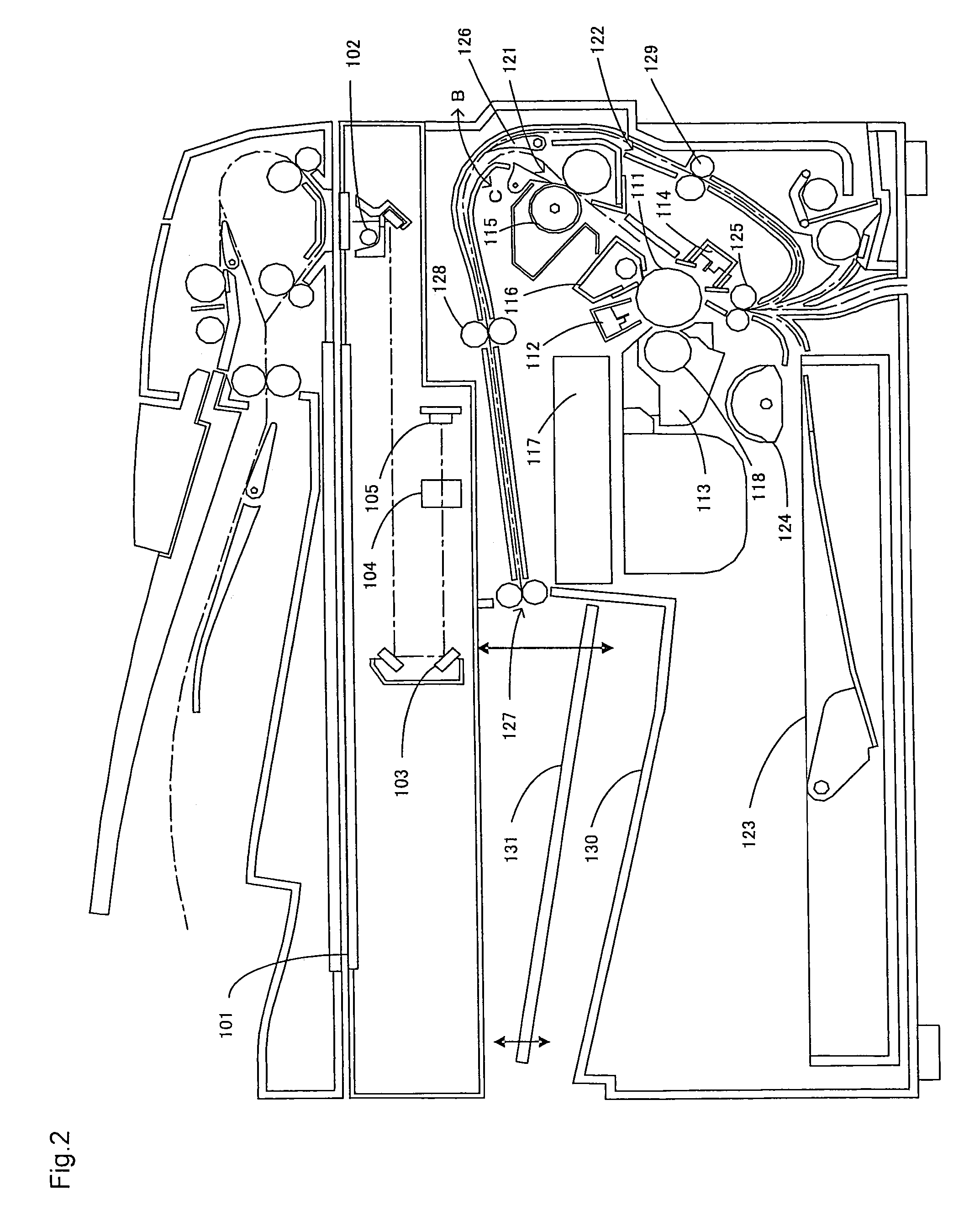
[0080]FIG. 2 is an explanatory view that illustrates an example of a configuration of the image forming apparatus according to the first embodiment. As shown in FIG. 2, the image forming apparatus according to the first embodiment is generally configured by a scanner section, a printing section, and a sheet transport section as the other section.

[0081]The scanner section irradiates an original with light and generates image data according to an image of the original from the reflected light. The printing section generates a visible image based on the image data generated by the scanner section, and prints this visible image on a predetermined transfer sheet (hereinafter, simply “sheet”). The sheet transport section supplies the sheet to the printing section and ejects the print...

second embodiment

[0086]In a second embodiment, a first example of ensuring a good stacking performance for stacking sheets by an action of a sheet presser arm and a sheet exit tray will be described.

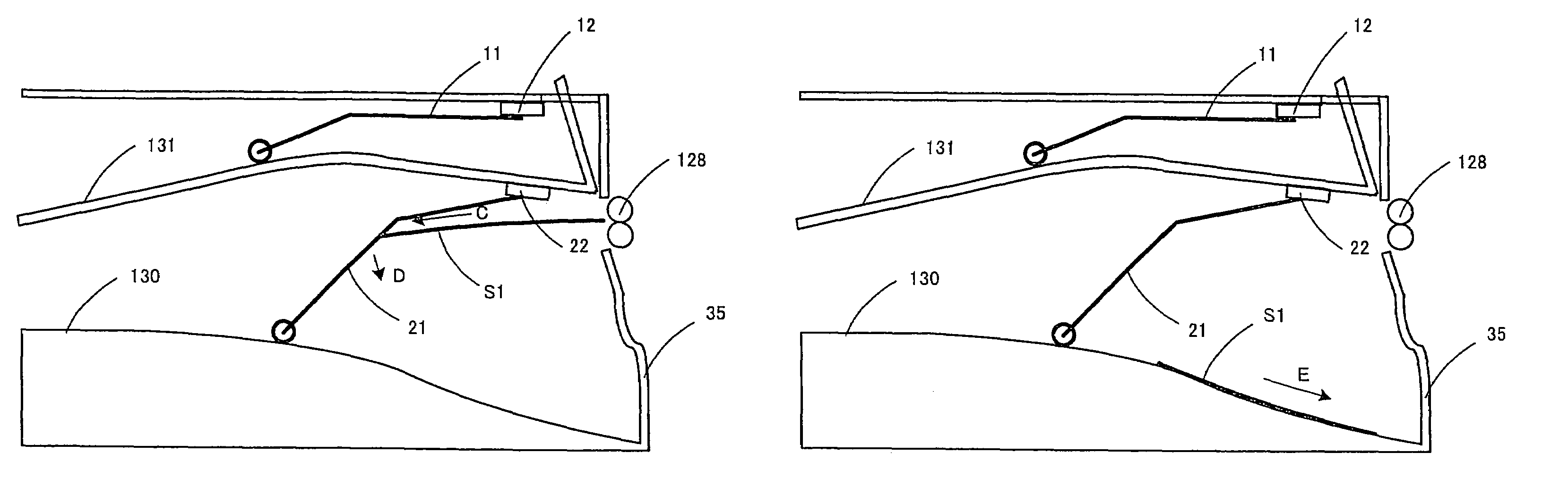
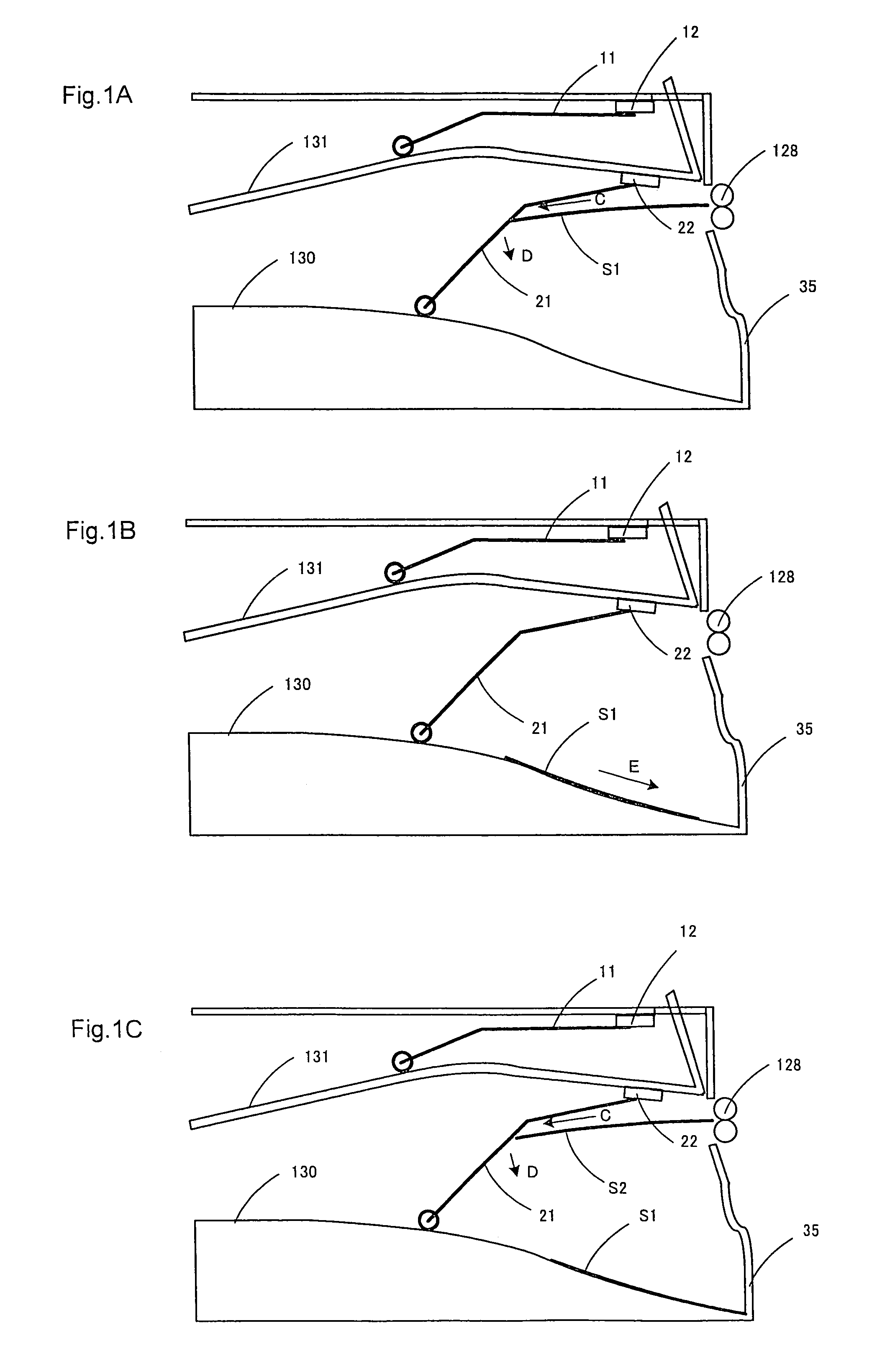
[0087]FIGS. 1A to 1C are explanatory views that illustrate a state in which ejected sheets of a first size are stacked in the sheet stacking device that includes the sheet presser arm according to the present invention. FIGS. 1A to 1C illustrate an instance in which the ejected sheets are stacked on the first sheet exit tray 130. A doglegged sheet presser arm 21 having a bend is arranged on the first sheet exit tray 130. One end of the arm 21 is fixed to an arm supporting member 22 arranged below the second sheet exit tray 131, and the other end thereof is in contact with the first sheet exit tray 130 via a roller. The arm 21 has flexibility and the roller on the free end is pressed against the first sheet exit tray 130 by an elastic force of the arm 21.

[0088]The action of the arm 21 and the first sheet ...

third embodiment

[0092]In a third embodiment, a second example of ensuring the good stacking performance for stacking sheets by the action of the sheet presser arm and the sheet exit tray will be described.

[0093]FIGS. 3A to 3D are explanatory views that illustrate a state in which ejected sheets S3 of a second size larger than the first size are stacked in the sheet stacking device that includes the sheet presser arm according to the present invention. The action of the arm 21 and the first sheet exit tray 130 on the sheet of the second size is as follows.

[0094]A sheet S3 transported while a front end thereof passes through the exit rollers 128 is moved in a direction of an arrow F while a traveling direction thereof is kept substantially horizontal by the transport force applied from the exit rollers 128 and “stiffness” of the sheet S3 even after the front end passes through the exit rollers 128. In case of the sheet S3, before a rear end of the sheet S3 separates from the exit rollers 128, therefo...


PUM


Abstract

A sheet stacking device includes: an evacuation section for transporting and ejecting sheets; a sheet exit tray for stacking the ejected sheets; an arm supporting member; and a sheet presser arm including a supported end at one end, a free end at the other end which is capable of pressing the sheets stacked on the sheet exit tray directly or via a contact member attached to the free end, and a flexure portion having flexibility between the supported end and the free end. The supported end is attached to the arm supporting member. The arm can apply, by the flexibility of the flexure portion, a pressing force to the sheets stacked on the sheet exit tray and a repulsive force to each of the ejected sheets when a front end of the ejected sheet strikes against the arm.

Description

CROSS-REFERENCE TO RELATED APPLICATION[0001]This application is related to Japanese patent application Nos. 2004-275670, 2004-275690 and 2004-275629 which were filed on Sep. 22, 2004, whose priorities are claimed under 35 USC §119, the disclosure of which are incorporated by reference in its entirety.BACKGROUND OF THE INVENTION[0002]1. Field of the Invention[0003]The present invention relates to a sheet stacking device and an image forming apparatus including the same.[0004]2. Description of the Related Art[0005]A sheet stacking device that stacks sheets output from an image forming apparatus or the like is required to orderly stack the sheets at a predetermined position while keeping an eject order of the sheets, that is, required for a good stacking performance. To this end, a technique for arranging a sheet presser arm that prevents an ejected sheet from projecting downstream of an ejection direction in a sheet reception tray is known (see, for example, Japanese Unexamined Patent...

Claims


Application Information

Patent Timeline
Patent Type & Authority Patents(United States)
IPC IPC(8): B65H31/00B65H31/26
CPCB65H31/24B65H31/26B65H2405/332B65H2801/06B65H2405/1111B65H2405/35
Inventor KANEKO, HIDETOSHIHATANAKA, MASATSUGUNAKAO, MOTOKAZUSHIRAISHI, YOSHINORIIZUMI, HIDESHIMORI, TOYOKAZUAKAGAWA, YUHI
Owner SHARP KK
Why Eureka
Try Eureka