Apparatus for removing dissolved and suspended contaminants from waste water

a technology of suspended contaminants and apparatus, which is applied in the direction of water cleaning, liquid displacement, separation processes, etc., can solve the problems of difficult time-consuming and difficult installation and maintenance of conventional catch basin traps for catch basins, and achieve the effect of blocking the passage of all waste water through the trap

Active Publication Date: 2010-03-30
GLYNNE MICHAEL J
View PDF22 Cites 21 Cited by
  • Summary
  • Abstract
  • Description
  • Claims
  • Application Information

AI Technical Summary

Benefits of technology

[0008]In a second embodiment, the device of the invention also arrests the flow of oil and oil based products, most specifically in the event of a spill. Oil absorbing particulate in the trap expands, thereby blocking the passage of all waste water through the trap.

Problems solved by technology

Installation and maintenance of conventional catch basin traps for catch basins is problematic.
Most conventional oil / gas traps are made of cast iron, which is very heavy and makes installation extremely difficult.
Often drilling into the concrete surrounding the drainage pipe is necessary, which is time-consuming and difficult.
In addition, conventional gas traps do not maintain an effective seal to prevent floating pollutants from entering the drain pipe.

Method used


Image

  • Apparatus for removing dissolved and suspended contaminants from waste water
  • Apparatus for removing dissolved and suspended contaminants from waste water
  • Apparatus for removing dissolved and suspended contaminants from waste water

Examples


Embodiment Construction

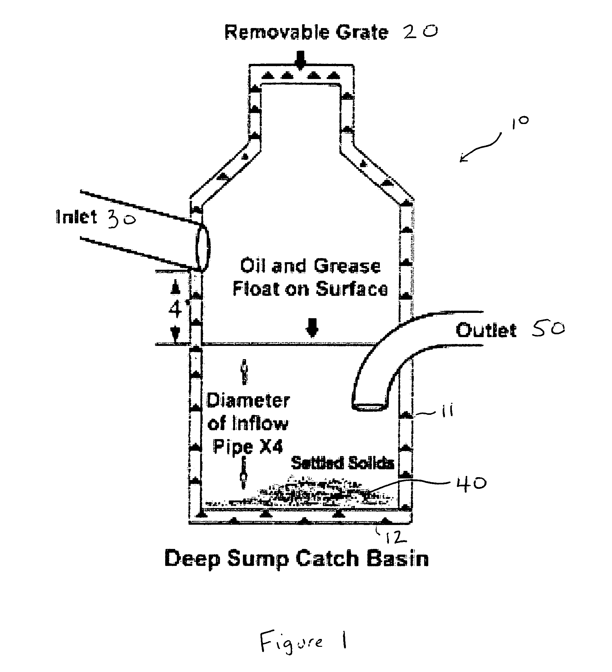
[0020]Catch basin traps are well known in the industry, and used in most catch basins to arrest the flow of pollutants into drainpipes and sewer lines. FIG. 1 illustrates a typical catch basin 10. The basin 10 is typically constructed with concrete walls 11 and a concrete base 12. At the top, typically a grate 20 or other entry means is located. Wastewater, as well as litter, oil, dirt and other pollutants, pass through the grate 20 and into the catch basin 10. Optionally, additional entry means 30 are also located within the catch basin. Solid wastes 40 that are heavier than water settle at the bottom of the catch basin 10. However, oil and other low density pollutants float on the top of the wastewater within the catch basin. To prevent these pollutants from entering outlet 50, various techniques are used. As shown in FIG. 1, a pipe having a bend so as to have its opening below the surface of the wastewater can be used to prevent the floating pollutants from entering outlet 50.

[00...


PUM

PropertyMeasurementUnit
diameteraaaaaaaaaa
diameteraaaaaaaaaa
diameteraaaaaaaaaa

Abstract

The present invention provides a method and apparatus for the treatment of waste water, particularly for the treatment and / or reduction of floating pollutants in storm water waste streams. The apparatus of the invention achieves a high containment level of floating pollutants compared to conventional oil / gas traps available for catch basin use. In a preferred embodiment, the device of the invention is a catch basin trap that arrests the flow of pollutants, particularly floating pollutants. The trap is designed and installed in such a manner that a sealed system is created, ensuring that all fluid flow (e.g., storm water discharge) must pass through the trap and cannot bypass the trap due to unreliable trap attachment mechanisms or unsealed joints. Containment of floating pollutants is achieved.

Description

[0001]This application claims priority of U.S. Provisional Application Ser. No. 60 / 670,564, filed Apr. 12, 2005, the disclosure of which is incorporated herein by reference.BACKGROUND OF THE INVENTION[0002]Catch basins are surface-level inlets to sewer systems that serve to allow storm water waste to enter a sewer system. Drainage and storm water is typically collected in catch basins buried in the ground. Water from rain or snow flows into the catch basin, where it is then diverted to a sewer or drainage line.[0003]Grates are usually present at the top surface of the catch basins to help reduce the amount of debris that enters the basin. Filters or traps are often employed to remove various pollutants and solids from the water, such as to minimize or eliminate offensive odors, prevent large solids from entering the catch basin, reduce pollutants, etc. Indeed, governmental regulations often dictate the acceptable levels of various pollutants such as sediment, hydrocarbons and debris...

Claims


Application Information

Patent Timeline
Patent Type & Authority Patents(United States)
IPC IPC(8): E03F5/14
CPCE03F5/14
Inventor GLYNNE, MICHAEL J.
Owner GLYNNE MICHAEL J
Why Eureka
Try Eureka