Mechanically and electrically connecting member

a technology of mechanical and electrical connection and connecting member, which is applied in the field of connecting member, can solve the problems of increasing the overall size and weight of the system, affecting the service life of the connecting member, and the inability to meet the requirements of the system, and achieves excellent mechanical and electrical connection. excellent

Active Publication Date: 2010-03-30
LG ENERGY SOLUTION LTD
View PDF7 Cites 19 Cited by
  • Summary
  • Abstract
  • Description
  • Claims
  • Application Information

AI Technical Summary

Benefits of technology

[0008]As a result of a variety of extensive and intensive studies and experiments to solve the problems as described above, the inventors of the present invention have developed a connecting member having a specific structure, and have found that the connecting member enables the manufacture of a compact-structured battery system having a plurality of battery modules, and, when an external force is applied to the battery system, the possibility of damage to the electrical connection of the battery system is greatly reduced through the efficient distribution of the force. Also, the inventors of the present invention have found that the connecting member can be preferably used for objects required to be mechanically and electrically connected with each other as well as a medium- or large-sized battery system.
[0009]Consequently, it is an object of the present invention to provide a connecting member enabling compact and excellent mechanical connection as well as stable electrical connection.
[0012]According to the present invention, the insulation body is positioned such that the connecting bar, which is integrally formed at or coupled to each object required to be mechanically and electrically connected, can be inserted into the connection hole, and is then coupled to the objects through the coupling holes using coupling units, such as bolts and nuts, thereby accomplishing mechanical and electrical connection of the objects. Consequently, the assembly and disassembly of the objects are very easily carried out. The mechanical connection between the objects is mainly accomplished by the insulation body, and the electrical connection between the objects is accomplished by the conductive strip. As a result, when an external force is applied to the objects, the electrical connection between the objects is not easily broken, the compact connection between the objects is accomplished. Furthermore, distinction between cathode and anode terminals is easily made, and therefore, the possibility of short circuit during the operation is greatly reduced.
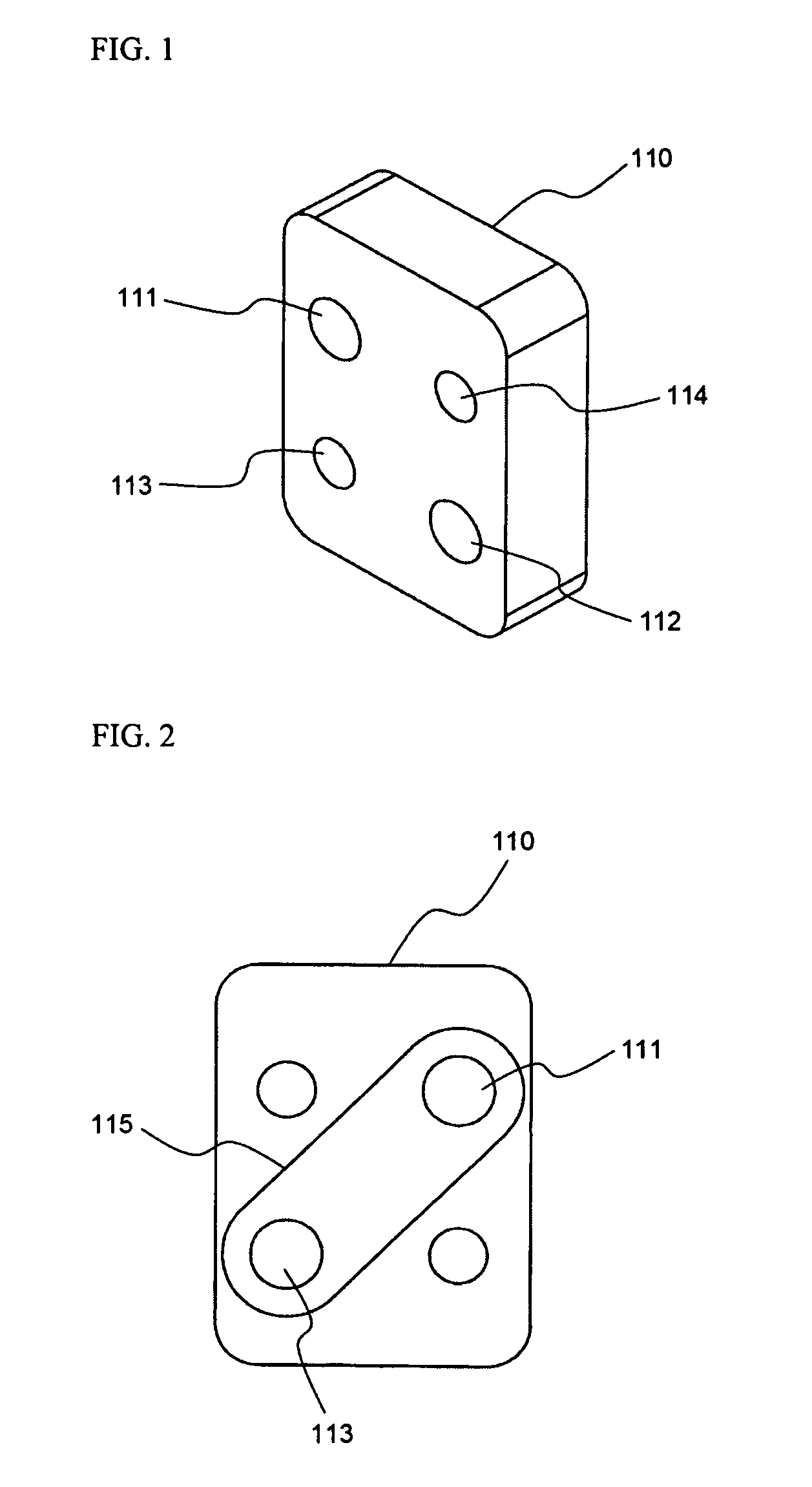
[0016]One of the characteristics of the present invention is that the conductive strip is mounted at the rear surface of the insulation body in the diagonal direction of the insulation body. It is preferable to reduce the length of the connecting member in order to accomplish a compact mechanical connection between two objects. In the case that the electrical connection parts of the objects are connected with each other by the connecting unit (the conductive strip of the present invention) in the horizontal direction, excessive load is applied to the conductive strip when an external force is applied to the objects or the connecting member, with the result that the conductive strip is easily broken. According to the present invention, since the conductive strip is in contact with the electrical connection parts (for example, the bus bars) of the object in the diagonal direction of the insulation body, a force causing breakage or distortion is not directly applied to the conductive strip when an external force is applied to the connecting member. Consequently, the compact mechanical connection between the two objects as well as the stable electrical connection between the two objects is accomplished.
[0021]After synthetically considering the entire disclosures of the patent application and the specification of the present invention, the medium- or large-sized battery system according to the present invention provides the very compact structure and the excellent mechanical and electrical connection.

Problems solved by technology

When a housing is used to improve mechanical and electrical connection such that the battery system can be mounted in the housing, however, the overall size and weight of the system are increased, which is not desirable.
However, most of the connecting members may be easily damaged when an external force is applied to the connecting members.

Method used


Image

  • Mechanically and electrically connecting member
  • Mechanically and electrically connecting member
  • Mechanically and electrically connecting member

Examples


Embodiment Construction

[0034]Now, a preferred embodiment of the present invention will be described in detail with reference to the accompanying drawings. It should be noted, however, that the scope of the present invention is not limited by the illustrated embodiment.

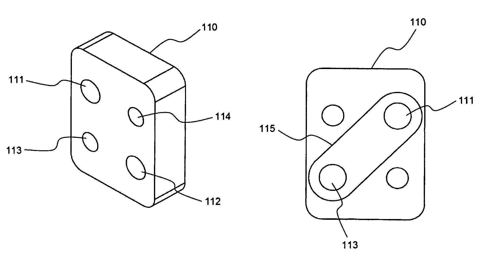
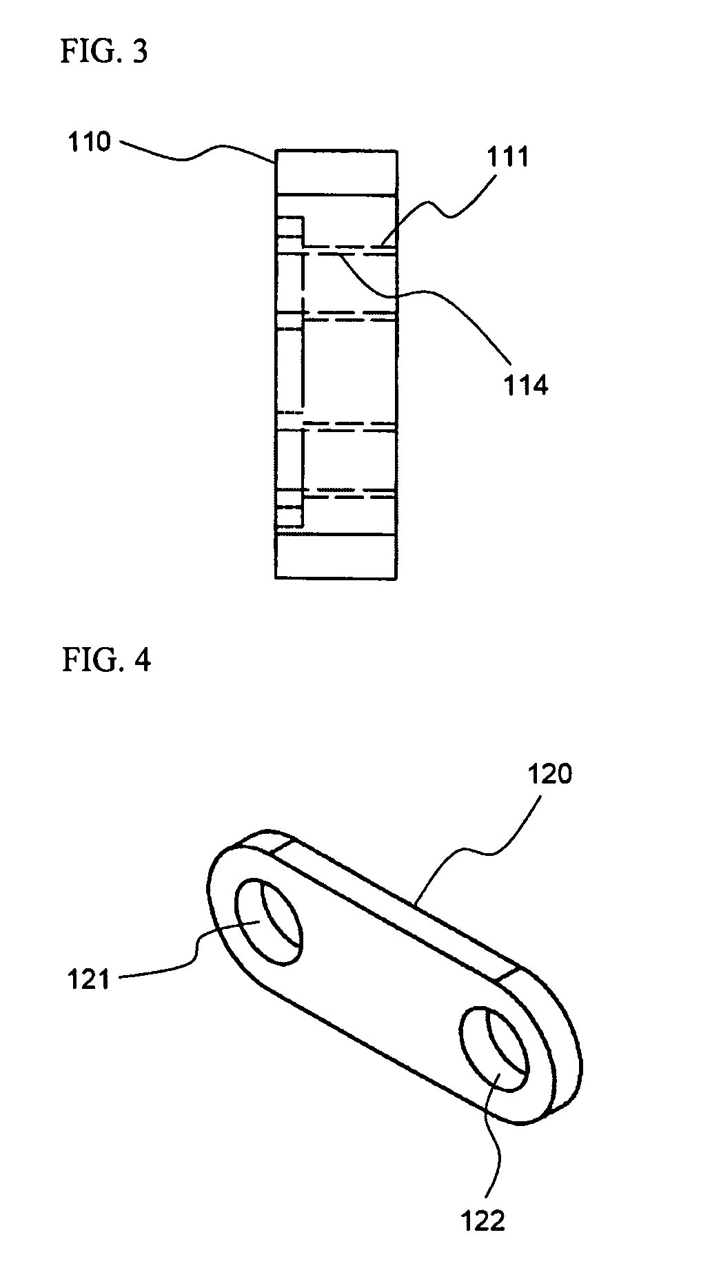
[0035]FIGS. 1 to 3 are a perspective view, a rear view, and a side view respectively illustrating an insulation body of a connecting member according to a preferred embodiment of the present invention, and FIG. 4 is a perspective view illustrating a conductive strip of a connecting member according to a preferred embodiment of the present invention.

[0036]Referring to these drawings, the mechanically and electrically connecting member according to the present invention comprises: an insulation body 110 formed in the shape of a rectangle; a conductive strip 120 formed in the shape of a plate; and a connecting bar 130 (see FIG. 6).

[0037]Preferably, the insulation body 110 is made of plastic resin having high tensile strength and high dimensiona...


PUM

PropertyMeasurementUnit
electricallyaaaaaaaaaa
conductiveaaaaaaaaaa
shapeaaaaaaaaaa

Abstract

Disclosed herein is a member for mechanically and electrically connecting two or more objects, including an insulation body having a plurality of coupling holes for coupling the objects formed therein, a plate-shaped conductive strip mounted at the rear surface of the insulation body in the diagonal direction of the insulation body while the conductive strip is isolated from the front surface of the insulation body, the conductive strip having connection holes formed at opposite ends thereof such that the connection holes communicate with the insulation body, and a connecting bar constructed such that the connecting bar can be inserted into the corresponding connection hole of the conductive strip while the strip is connected to the objects. The connecting member accomplishes excellent mechanical connection and stable electrical connection of objects, easy assembly and disassembly, and low possibility of short circuits. Furthermore, the objects can be connected with each other in a compact structure, and therefore, the connecting member according to the present invention can be preferably used to connect battery modules constituting a medium- or large-sized battery system, especially, for electric vehicles or hybrid electric vehicles.

Description

FIELD OF THE INVENTION[0001]The present invention relates to a member for mechanically and electrically connecting two or more objects, and, more particularly, to a member for mechanically and electrically connecting two or more objects, comprising: an insulation body having a plurality of coupling holes for coupling the objects formed therein; a plate-shaped conductive strip mounted at the rear surface of the insulation body in the diagonal direction of the insulation body while the conductive strip is isolated from the front surface of the insulation body, the conductive strip having connection holes formed at opposite ends thereof such that the connection holes communicate with the insulation body; and a connecting bar constructed such that the connecting bar can be inserted into the corresponding connection hole of the conductive strip while the strip is connected to the objects.BACKGROUND OF THE INVENTION[0002]Recently, a secondary battery, which can be charged and discharged, ...

Claims


Application Information

Patent Timeline
Patent Type & Authority Patents(United States)
IPC IPC(8): H01M2/10B60R16/04H01M6/42H01R13/648H01R3/00H01R31/08H01R4/50H01R4/66H01M50/529H01M50/204
CPCH01M2/1083H01M2/1077Y02E60/10H01M50/204H01M50/20H01M2220/20
Inventor YOON, JUNILLRO, JONG-YULJUNG, DO YANGYU, JISANG
Owner LG ENERGY SOLUTION LTD
Why Eureka
Try Eureka