Head suspension assembly and storage device

a technology of suspension assembly and storage device, which is applied in the direction of magnetic recording, data recording, instruments, etc., can solve the problems of inaccurate positioning of the head slider, and achieve the effect of reducing resonan

Inactive Publication Date: 2010-03-30
TOSHIBA STORAGE DEVICE CORP
View PDF10 Cites 9 Cited by
  • Summary
  • Abstract
  • Description
  • Claims
  • Application Information

AI Technical Summary

Benefits of technology

[0008]The head suspension assembly allows the load beam to have a narrower width based on the narrow section. The load beam is thus allowed to enjoy a reduced weight. The mass is reduced at a position distanced from the centerline of the load beam. This results in a reduction in the inertial force around the centerline in the load beam. The inventors have demonstrated that the resonance frequency of the first torsion mode is allowed to fall in a higher frequency range. The resonance of the head suspension assembly can be reduced.
[0009]The load beam is bonded to the hinge plate at the wide section and the narrow section. The hinge plate is designed to extend farther than ever. The hinge plate thus serves to enhance the rigidity of the narrow section. The load beam is prevented from a reduction in the rigidity. The inventors have demonstrated that the resonance frequency of the sway mode is reliably prevented from a shift to a lower frequency range.
[0010]The head suspension assembly may further comprise a rib standing upright from the side edge of the narrow section. In addition, a rib may stand upright from the side edge of the hinge plate. Likewise, the head suspension assembly may further comprise a rib standing upright from the rear edge of the wide section. The hinge plate is bonded to the narrow section as described above. These ribs contribute to enhancement of the rigidity of the load beam. The load beam is surely prevented from a reduction in the rigidity.
[0011]The front end of the hinge plate may be located between the rear end of the narrow section and a protrusion defined at the front end of the narrow section to receive the head slider. The front end of the hinge plate can be located at an intermediate position between the protrusion and the rear end of the narrow section, for example. It has been observed that deformation of the load beam is maximized at the center of the load beam in the first torsion mode. The front end of the hinge plate is located at a position closer to the center. The hinge plate thus serves to further reinforce an enhancement of the rigidity of the load beam. The load beam is prevented from deformation at the center to the utmost. The resonance frequency of the sway mode is reliably prevented from a shift to a lower frequency range.

Problems solved by technology

The resonance of the head suspension assembly results in an inaccurate positioning of the head slider.

Method used


Image

  • Head suspension assembly and storage device
  • Head suspension assembly and storage device
  • Head suspension assembly and storage device

Examples


Embodiment Construction

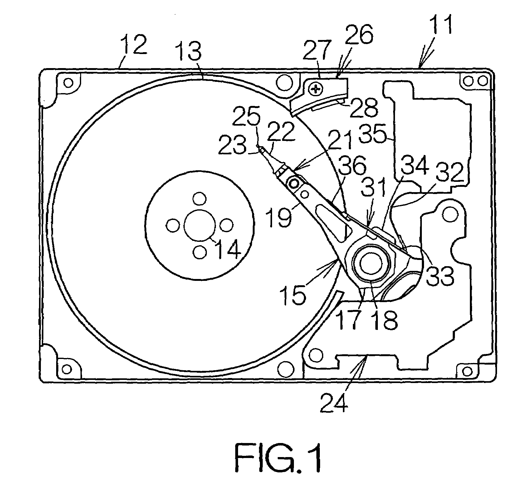
[0030]FIG. 1 schematically illustrates the inner structure of a hard disk drive, HDD, 11 as an example of a storage medium drive or a storage device according to the present invention. The hard disk drive 11 includes a box-shaped enclosure body 12 defining an inner space in the form of a flat parallelepiped, for example. The enclosure body 12 may be made of a metallic material such as aluminum, for example. Molding process may be employed to form the enclosure body 12. An enclosure cover, not shown, is coupled to the enclosure body 12. An inner space is defined between the enclosure body 12 and the enclosure cover. Pressing process may be employed to form the enclosure cover out of a plate material, for example. The enclosure body 12 and the enclosure cover in combination establish an enclosure.

[0031]At least one magnetic recording disk 13 as a storage medium is incorporated in the enclosure body 12. The magnetic recording disk or disks 13 are mounted on the driving shaft of a spind...


PUM

PropertyMeasurementUnit
thicknessaaaaaaaaaa
thicknessaaaaaaaaaa
thicknessaaaaaaaaaa

Abstract

A hinge plate is bonded to a base plate and a load beam in a head suspension assembly. The load beam includes a wide section and a narrow section extending forward from the front end of the wide section. The head suspension assembly allows the load beam to have a narrower width based on the narrow section. The load beam is thus allowed to enjoy a reduced weight. The mass is reduced at a position distanced from the centerline of the load beam. This results in a reduction in the inertial force around the centerline in the load beam. The inventors have demonstrated that the resonance frequency of the first torsion mode is allowed to fall in a higher frequency range. The resonance of the head suspension assembly can be reduced.

Description

BACKGROUND OF THE INVENTION[0001]1. Field of the Invention[0002]The present invention relates to a head suspension assembly incorporated in a storage device such as hard disk drive, HDD.[0003]2. Description of the Prior Art[0004]A head suspension assembly includes a base plate and a load beam distance d forward from the base plate at a predetermined interval. A leaf spring is utilized to couple the base plate and the load beam. A substrate is attached to the load beam. Ahead slider is supported on the front or tip end of the substrate. The leaf spring serves to urge the head slider toward a magnetic recoding disk.[0005]The head slider is designed to read out position information from the magnetic recording disk in the hard disk drive. The position information is utilized to position the head slider. A so-called feedback control is effected. The resonance of the head suspension assembly results in an inaccurate positioning of the head slider. In particular, the resonance of a first t...

Claims


Application Information

Patent Timeline
Patent Type & Authority Patents(United States)
IPC IPC(8): G11B21/16
CPCG11B5/4826G11B5/4833G11B21/21
Inventor KIDO, TAKUMAWATANABE, TORU
Owner TOSHIBA STORAGE DEVICE CORP
Why Eureka
Try Eureka