1×N wavelength selective switch

a wavelength selective switch and wavelength technology, applied in the field of optical switching, can solve the problems of inflexible arrangement in regards to wavelength splitting ability, high per-wavelength cost for a small number of wavelengths, and inability to meet so as to alleviate the alignment requirements of micro mirrors

Active Publication Date: 2010-03-30
ALCATEL-LUCENT USA INC +1
View PDF9 Cites 7 Cited by
  • Summary
  • Abstract
  • Description
  • Claims
  • Application Information

AI Technical Summary

Benefits of technology

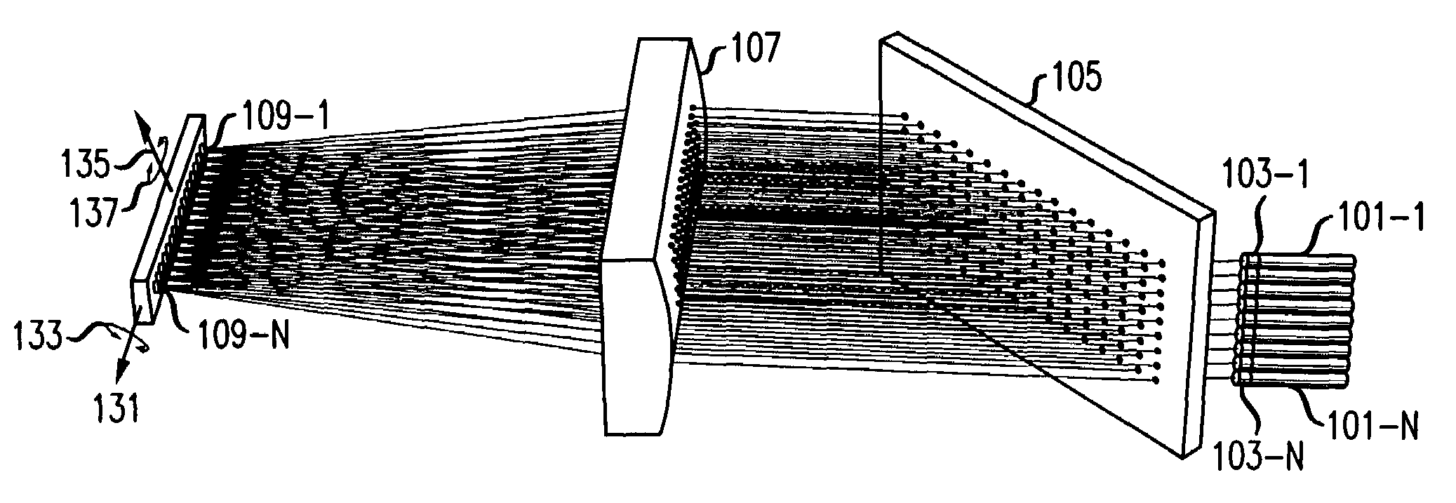
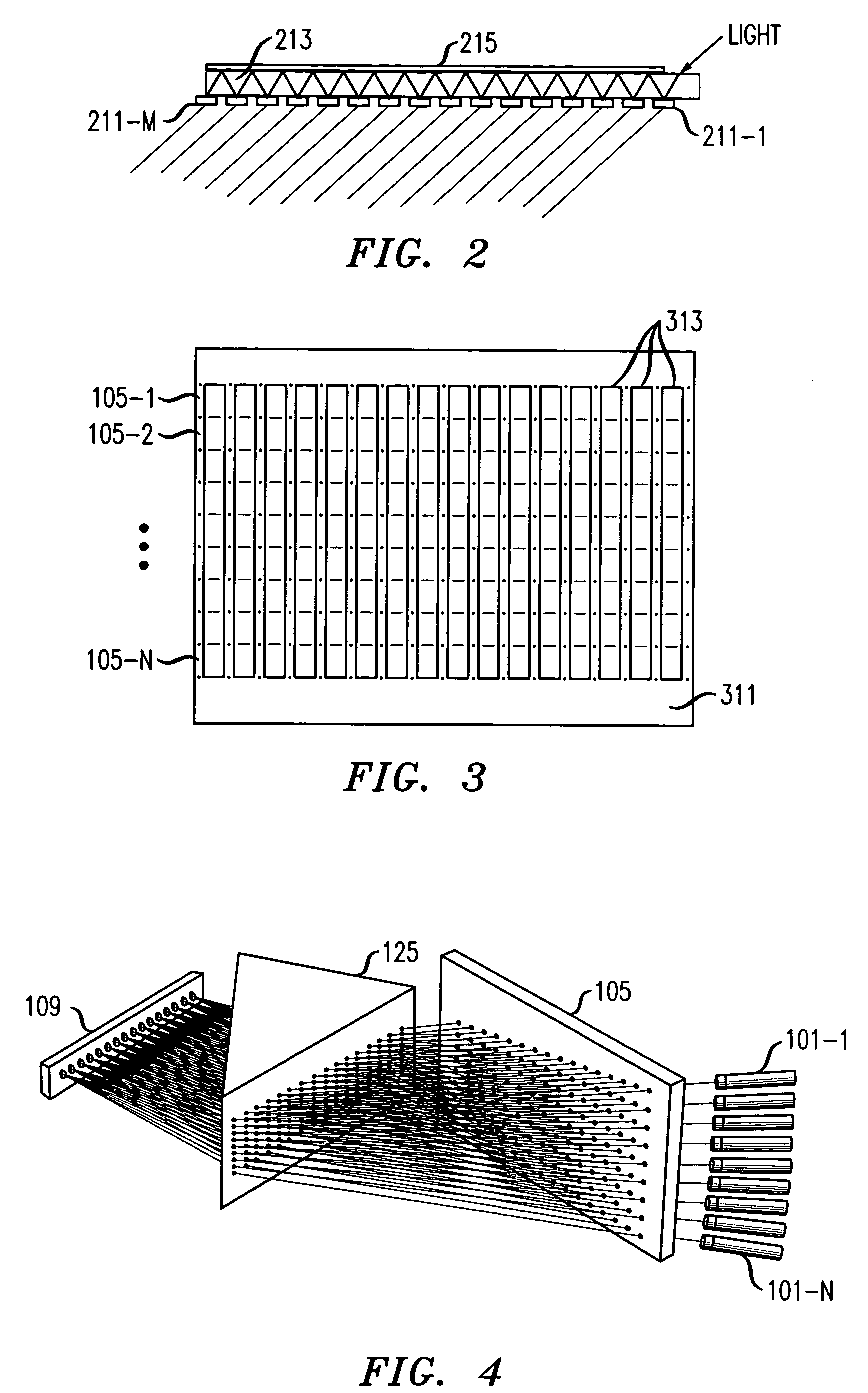
[0010]A wavelength sieve / combiner may also be implemented in a free-space version by suspending appropriately the necessary filter and reflective elements. Also, substrates other than glass may be employed, so long as they do not cause undue attenuation of the wavelengths of interest.
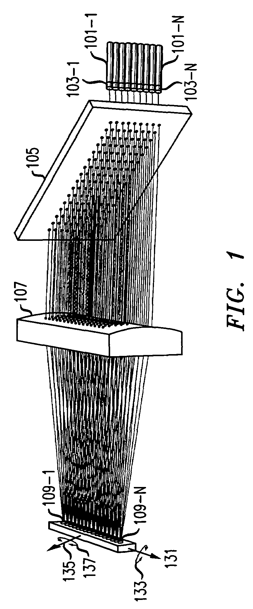
[0012]Primarily, the micro mirrors are arranged to tilt about a first axis, which is the axis that the mirrors would have in common when stacked one on top of the other. It is also advantageous, for purposes of hitless switching and to alleviate alignment requirements, for the micro mirrors to be able to tilt around a second axis, orthogonal to the first axis. Tilting about the second axis is used for hitless switching because such tilting essentially takes the micro mirror “offline” by reflecting the beam out of the surface of a sieve / combiner. The micro mirror is then tilted around its first axis to the desired new position that accommodates a change in output requirements, and then tilted around the second axis back “online”, so the beam now hits the new appropriate thin film filter on the sieve / combiner. Advantageously, while the micro mirror is tilted offline, its beam will not be accidentally directed to an incorrect output fiber, which may otherwise occur should the tilt of the mirror about the first axis be changed while the micro mirror is online. Alignment requirements of the micro mirrors are alleviated because they may be tilted about the second axis once the system is operational to compensate for any slight misalignment.

Problems solved by technology

If this criterion is not met, contention will occur.
Disadvantageously, such an arrangement is too expensive for a small number of wavelengths, because it requires the same costly precise alignment of all components independent of the number of wavelengths employed, so the per-wavelength cost is high for a small number of wavelengths.
Such an arrangement is also relatively inflexible in regards to its wavelength splitting abilities.
Furthermore, if there is a gap between the mirrors, there will be a gap between the wavelengths.

Method used


Image

  • 1×N wavelength selective switch
  • 1×N wavelength selective switch
  • 1×N wavelength selective switch

Examples


Embodiment Construction

[0024]The following merely illustrates the principles of the invention. It will thus be appreciated that those skilled in the art will be able to devise various arrangements that, although not explicitly described or shown herein, embody the principles of the invention and are included within its spirit and scope. Furthermore, all examples and conditional language recited herein are principally intended expressly to be only for pedagogical purposes to aid the reader in understanding the principles of the invention and the concepts contributed by the inventor(s) to furthering the art, and are to be construed as being without limitation to such specifically recited examples and conditions. Moreover, all statements herein reciting principles, aspects, and embodiments of the invention, as well as specific examples thereof, are intended to encompass both structural and functional equivalents thereof. Additionally, it is intended that such equivalents include both currently known equivale...


PUM


Abstract

A device employing at least one wavelength sieve / combiner that operates on discrete wavelength units and is optically interposed between an array of fibers and an array of micro mirrors which may be configured to act as in a multiplexing mode, a demultiplexing mode, a broadcast mode, and combinations of such modes. Each wavelength sieve / combiner can split a wavelength division multiplexed (WDM) beam into various discrete wavelength unit beams, combine various discrete wavelength unit beams into a WDM beam, or cause multiple copies of part or all of the wavelengths to be supplied as outputs. Typically, each fiber is associated with one wavelength sieve / combiner. Preferably, the beams between a wavelength sieve / combiner and the micro mirror array should be converging to the plane of the micro mirror array.

Description

TECHNICAL FIELD[0001]This invention relates to the art of optical switching, and more particularly, to the switching of various wavelengths of a wavelength division multiplexed optical signal from at least one input port to one or more output ports, and vice-versa.BACKGROUND OF THE INVENTION[0002]The transmission capacity of fiber-optic communication systems has been increased significantly by the use of wavelength division multiplexing (WDM) techniques. In a WDM communication system, multiple channels—where each channel is differentiated by using a unique wavelength of light—carry modulated optical signals in a single optical fiber between a transmitter and a receiver. The transmitter uses an optical multiplexer to combine multiple channels into the fiber for transmission, and the receiver uses an optical demultiplexer to separate the optical channels for detection. A typical optical demultiplexer (demux) contains a single input port and multiple output ports, where each optical ch...

Claims


Application Information

Patent Timeline
Patent Type & Authority Patents(United States)
IPC IPC(8): G02B6/00G02B6/26G02B6/28G02B6/32G02B6/42G02B26/08G02B6/34G02B6/35
CPCG02B6/29367G02B6/29395G02B6/3518G02B6/3558G02B6/356
Inventor KOZHEVNIKOV, MICHAELNEILSON, DAVID THOMASRYF, ROLAND
Owner ALCATEL-LUCENT USA INC
Why Eureka
Try Eureka