Optical fiber interconnection devices and systems using same

a technology of optical fiber and interconnection devices, which is applied in the direction of optical elements, multiplex communication, instruments, etc., can solve the problems of difficult to effectively manage the cabling in data centers for such networks, high cost of floor space, and increased system spa

Active Publication Date: 2010-03-30
CORNING OPTICAL COMM LLC
View PDF59 Cites 76 Cited by
  • Summary
  • Abstract
  • Description
  • Claims
  • Application Information

AI Technical Summary

Problems solved by technology

In a traditional network environment that includes a data center, floor space (e.g. the 24″×24″ raised floor tile within a data center) comes at a very expensive premium.
Therefore, each time passive and active fiber-optic equipment completely fills this space, new space is required for the system to grow.
Consequently, it is difficult to effectively manage the cabling in data centers for such networks.
For example, it is sometimes desirable to use line cards with 16 and 32 port counts, but these are not directly suitable for use with 12-fiber-based cabling systems.

Method used


Image

  • Optical fiber interconnection devices and systems using same
  • Optical fiber interconnection devices and systems using same
  • Optical fiber interconnection devices and systems using same

Examples


Embodiment Construction

[0037]Reference is now made in detail to the present preferred embodiments of the invention, examples of which are illustrated in the accompanying drawings. Whenever possible, like or similar reference numerals are used throughout the drawings to refer to like or similar parts. It should be understood that the embodiments disclosed herein are merely examples, each incorporating certain benefits of the present invention. Various modifications and alterations may be made to the following examples within the scope of the present invention, and aspects of the different examples may be mixed in different ways to achieve yet further examples. Accordingly, the true scope of the invention is to be understood from the entirety of the present disclosure, in view of but not limited to the embodiments described herein.

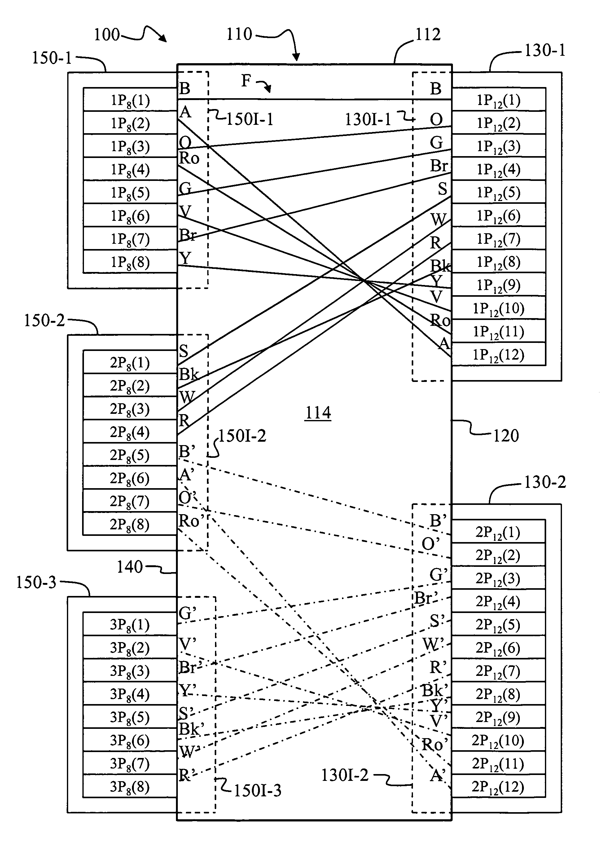
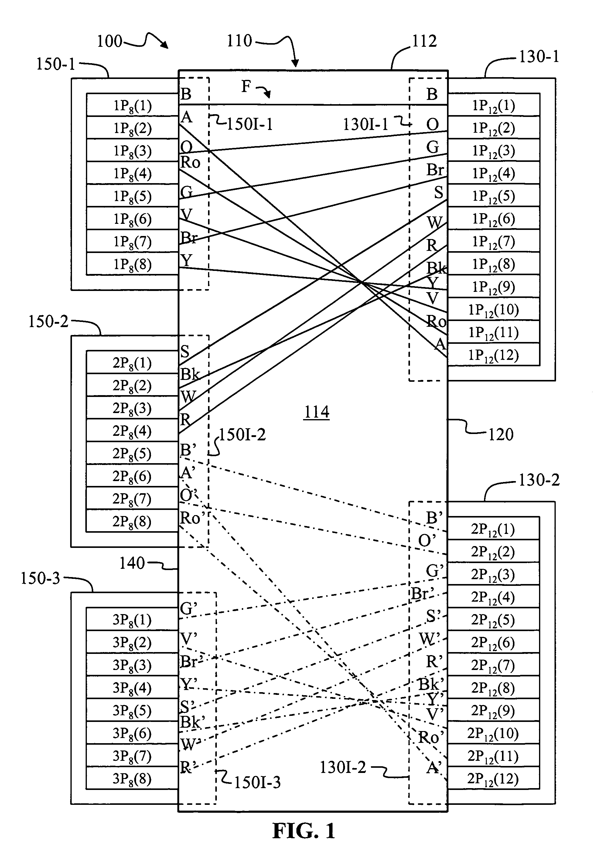
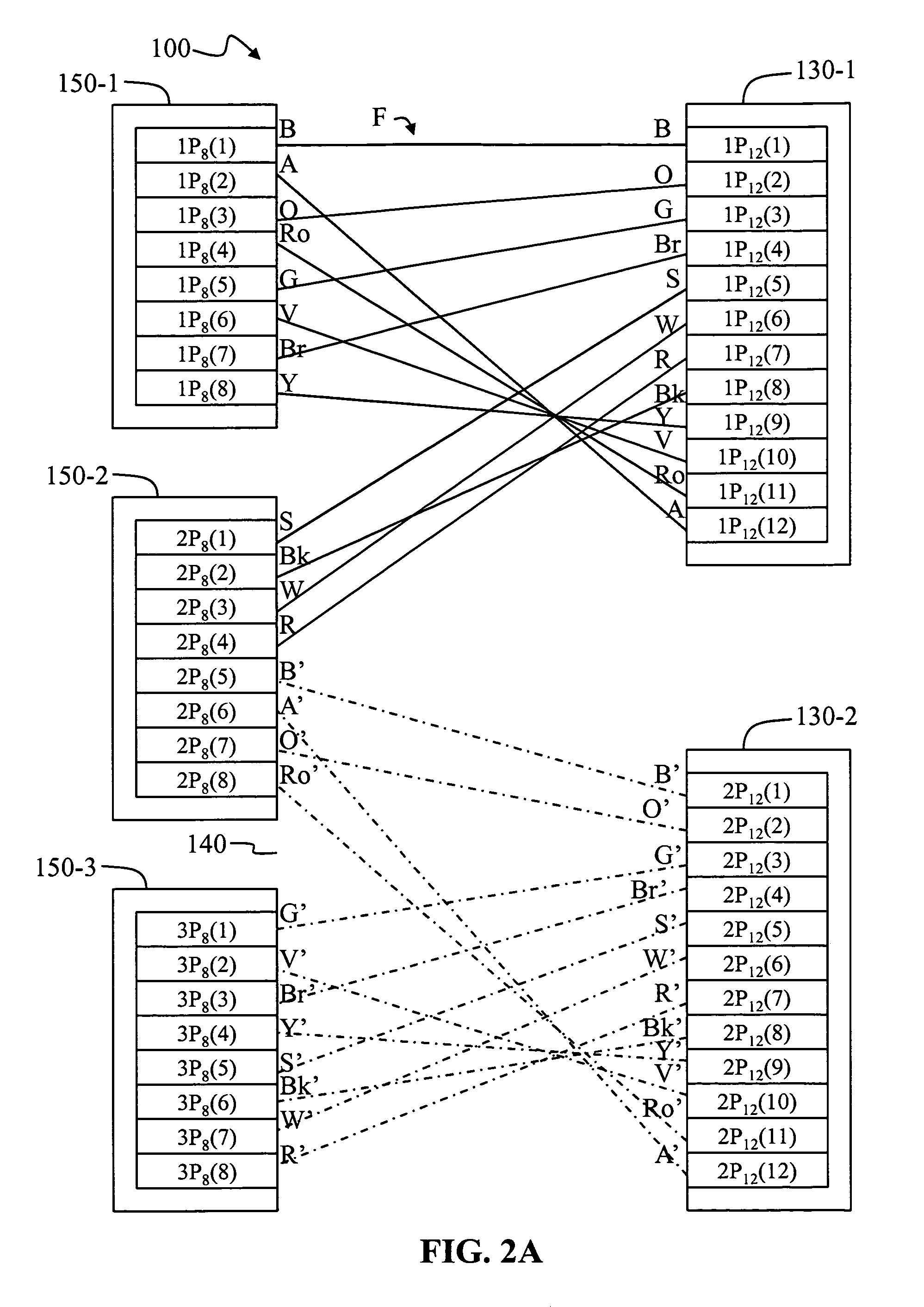
[0038]The present invention is directed to a conversion device configured to convert or otherwise interconnect two connectors (or n multiples thereof) each having twelve fibers (a...


PUM


Abstract

Optical fiber interconnection devices, which can take the form of a module, are disclosed that include an array of optical fibers and multi-fiber optical-fiber connectors, for example, two twelve-port connectors or multiples thereof, and three eight-port connectors or multiples thereof. The array of optical fibers is color-coded and is configured to optically interconnect the ports of the two twelve-port connectors to the three eight-port connectors in a manner that preserves transmit and receive polarization. In one embodiment, the interconnection devices provide optical interconnections between twelve-fiber optical connector configurations to eight-fiber optical connector configurations, such as from twelve-fiber line cards to eight-fiber line cards, without having to make structural changes to cabling infrastructure. In one aspect, the optical fiber interconnection devices provide a migration path from duplex optics to parallel optics.

Description

RELATED APPLICATIONS[0001]This application claims the benefit of priority under 35 U.S.C. § 119(e) of U.S. Parent Provisional Application Ser. No. 61 / 010,807 filed on U.S. Parent Provisional Application Filing Date of Jan. 11, 2008, which application is incorporated by reference herein.FIELD OF THE INVENTION[0002]The present invention relates to optical fiber interconnection devices configured to interconnect multi-fiber, optical fiber connectors and, in one exemplary embodiment, to interconnect two 12-fiber connectors, or multiples thereof, with three 8-fiber connectors, or multiples thereof.BACKGROUND OF THE INVENTION[0003]Conventional optical fiber cables comprise optical fibers that conduct light used to transmit voice, video, and data information. An optical ribbon includes a group of optical fibers that are coated with a ribbon common layer, which common layer may be of the ultraviolet (UV) light curable type. Typically, such a ribbon common layer is extruded about a group of ...

Claims


Application Information

Patent Timeline
Patent Type & Authority Patents(United States)
IPC IPC(8): G02B6/26G02B6/42
CPCG02B6/3897G02B6/4453G02B6/3608G02B6/4472
Inventor BURNHAM, WILLIAM R.DENNIS, ROBERT W.UGOLINI, ALAN W.COOKE, TERRY L.KLAVUHN, TORY A.
Owner CORNING OPTICAL COMM LLC
Why Eureka
Try Eureka