Shaft coupling

a shaft and shaft technology, applied in the direction of shafts, yielding couplings, shafts, etc., can solve the problems of increasing the size of the entire apparatus, affecting the smooth transmission of power, and reducing the efficiency of the shaft, so as to reduce the rattling of the rolling elements, increase the power, and smooth the effect of transmission

Active Publication Date: 2010-04-06
NTN CORP +1
View PDF19 Cites 16 Cited by
  • Summary
  • Abstract
  • Description
  • Claims
  • Application Information

AI Technical Summary

Benefits of technology

[0009]An object of the invention is to provide a shaft coupling which is short in axial dimension, which can transmit large power between shafts even if the offset amount of the shafts is large, and which is less expensive and can be assembled easily.

Problems solved by technology

Oldham couplings have, however, a problem in that if large power is transmitted between the two shafts, friction surfaces of sliders disposed between the two shafts cannot always be lubricated sufficiently, thus impairing smooth transmission of power.
Also, this arrangement does not permit a large offset (diametrical distance between the axes) of the two shafts.
This increases the size of the entire apparatus.
But in this type of shaft coupling, a large number of direct-acting guides are necessary, so that the manufacturing cost of the entire coupling tends to be high.
It is therefore troublesome and time-consuming to mount the direct-acting guides with high accuracy such that their guide member and rail member are smoothly movable relative to each other.

Method used


Image

  • Shaft coupling
  • Shaft coupling
  • Shaft coupling

Examples


Embodiment Construction

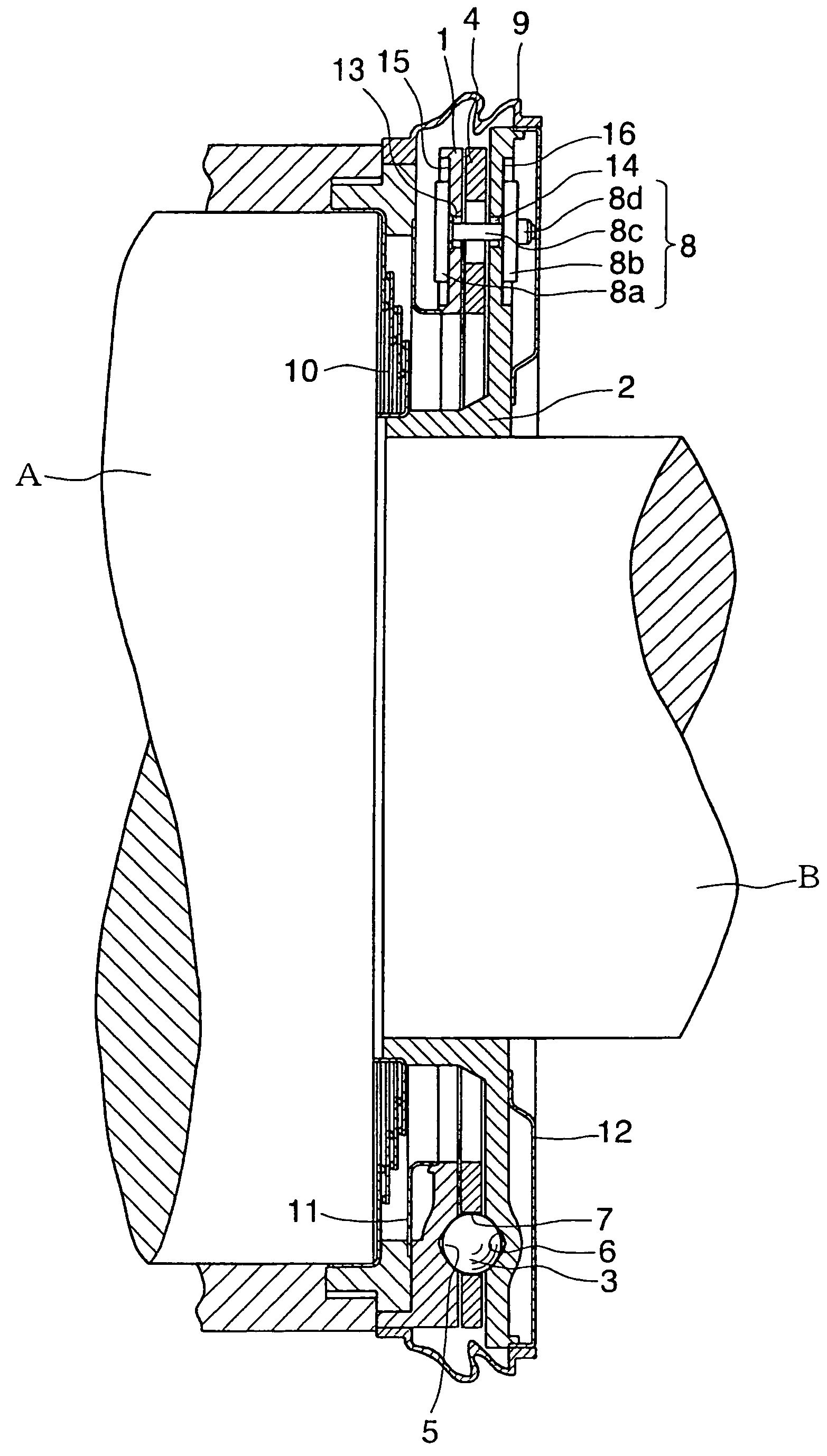
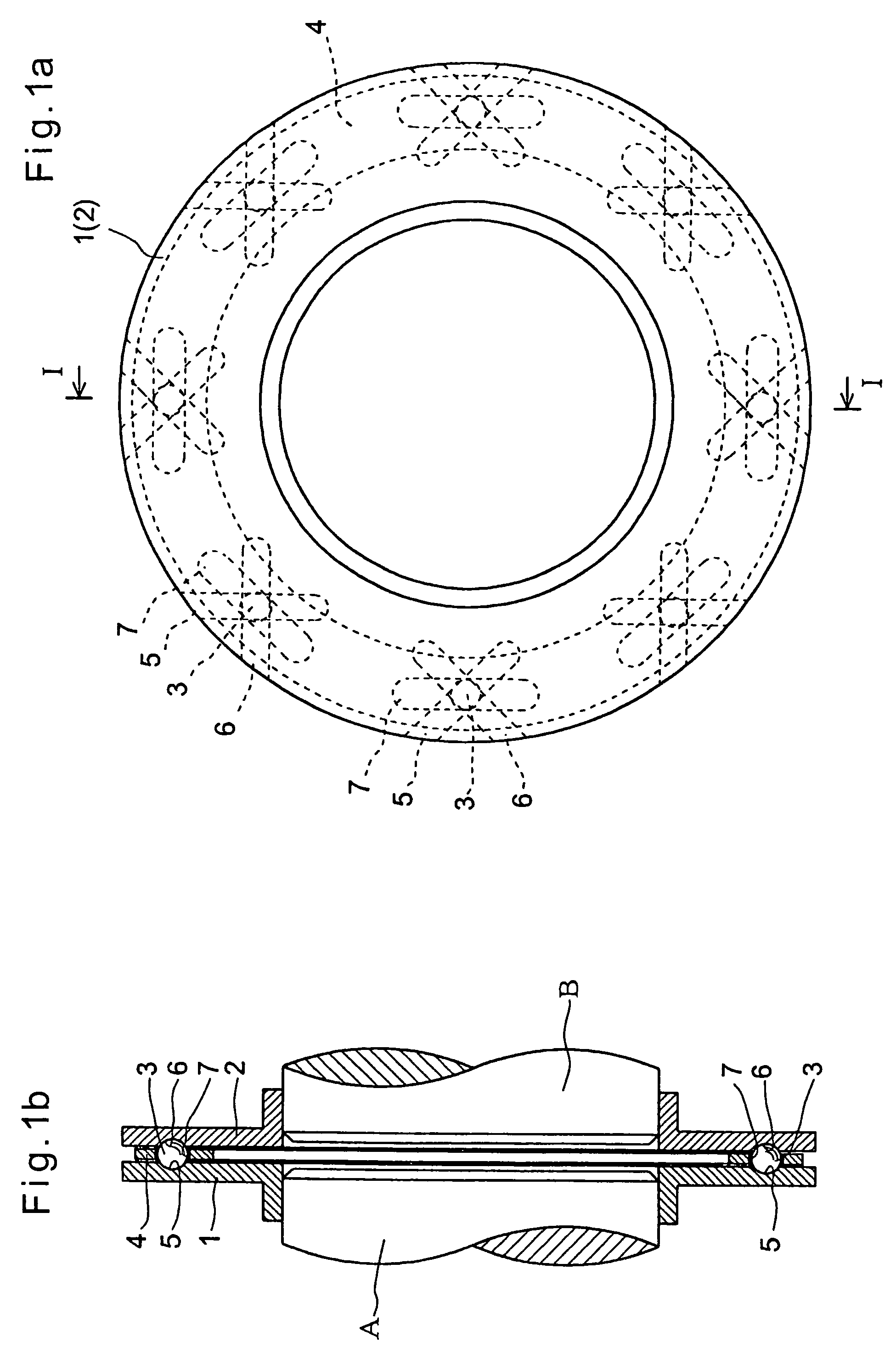
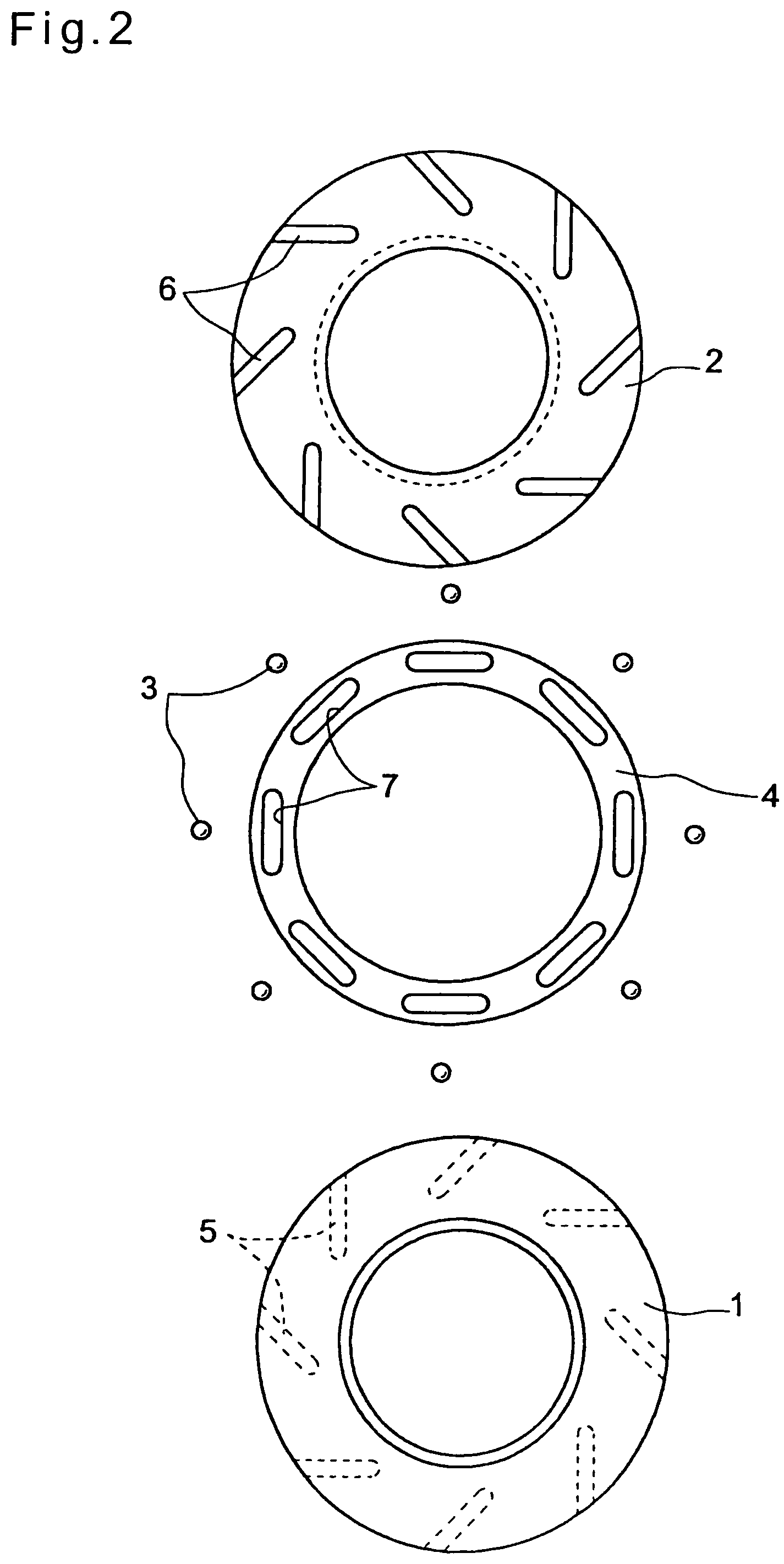
[0044]Now referring to FIGS. 1(a) to 8(b), the embodiments of the present invention are described. FIGS. 1(a) to 3(b) show the shaft coupling of the first embodiment, which comprises, as shown in FIGS. 1(a), 1(b) and 2, plates 1 and 2 as rotary members that are fitted on opposed ends of input and output shafts A and B, respectively, that are equal in diameter and having their central axes extending parallel to each other, a plurality of steel balls 3 as rolling elements that are disposed between the plates 1 and 2, and a retainer 4 that restricts radial movements of the steel balls 3. Power is transmitted between the plates 1 and 2 through the steel balls 3. The plates 1 and 2 and the retainer 4 are made of a metallic material. The plates 1 and 2, retainer 4 and steel balls 3 have their surfaces subjected to heat treatment or hardening treatment such as shot peening. In FIG. 1, for simplicity, the input and output shafts A and B are shown to be aligned with each other. But ordinaril...


PUM


Abstract

A shaft coupling includes plates fitted on ends of input and output shafts, respectively. A plurality of guide grooves are formed in the opposed surfaces of the plates, respectively, so that each of the grooves extends perpendicular to the corresponding groove formed in the other plate. A steel ball is disposed between each pair of guide grooves of the plates at a portion where the pair of grooves cross each other. When the steel balls are pushed by the driving plate, they push the driven plate while rolling in the guide grooves, with their movements restricted by a retainer in the radial direction of the plates. Thus, large power can be smoothly transmitted between the rotary members with less frictional resistance. The offset amount can be changed easily. Between the plates, there are only the steel balls and the retainer.

Description

BACKGROUND OF THE INVENTION[0001]1. Technical Field[0002]The present invention relates to a shaft coupling through which two shafts are coupled together so that power is transmitted therebetween.[0003]2. Background Art[0004]Shaft couplings are widely different in structure from each other depending on the positional relationship between driving and driven shafts which are coupled together through each shaft coupling so that power is transmitted from the driving shaft to the driven shaft. Typically, such two shafts are positioned so as to be aligned with each other, cross each other, or be parallel to (and not aligned with) each other.[0005]Among shaft couplings through which two parallel shafts are coupled together, Oldham couplings are well-known. Oldham couplings have, however, a problem in that if large power is transmitted between the two shafts, friction surfaces of sliders disposed between the two shafts cannot always be lubricated sufficiently, thus impairing smooth transmiss...

Claims


Application Information

Patent Timeline
Patent Type & Authority Patents(United States)
IPC IPC(8): F16D3/04F16D3/06
CPCF16D3/04
Inventor NOZAKI, TAKASHIHAKAMATA, HIROYUKISONE, KEISUKEHAYAMA, YOSHIHIKO
Owner NTN CORP
Why Eureka
Try Eureka