
Power control apparatus

a power control and power supply technology, applied in the direction of electric power, electric vehicles, transportation and packaging, etc., can solve the problems of inconvenient use, easy crash of the electronic device b>110/b>, etc., to increase the efficiency of power use, and ensure the safety of the electronic devi

Active Publication Date: 2010-04-06
COMPAL ELECTRONICS INC
View PDF6 Cites 8 Cited by
  • Summary
  • Abstract
  • Description
  • Claims
  • Application Information

AI Technical Summary

Benefits of technology

This solution ensures safe operation and increased power use efficiency by preventing sudden shutdowns and maintaining stable power distribution, while also saving energy by dynamically adjusting power output based on system requirements.

Problems solved by technology

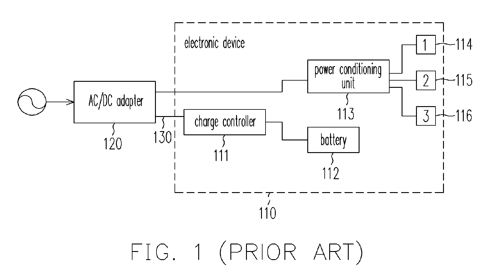
However, when the electronic device 110 is overloaded, if the AC / DC adapter 120 stops supplying power to the system 110 immediately, the electronic device 110 could easily crash, which is very inconvenient for users.

Method used


Image

  • Power control apparatus
  • Power control apparatus
  • Power control apparatus

Examples


Embodiment Construction

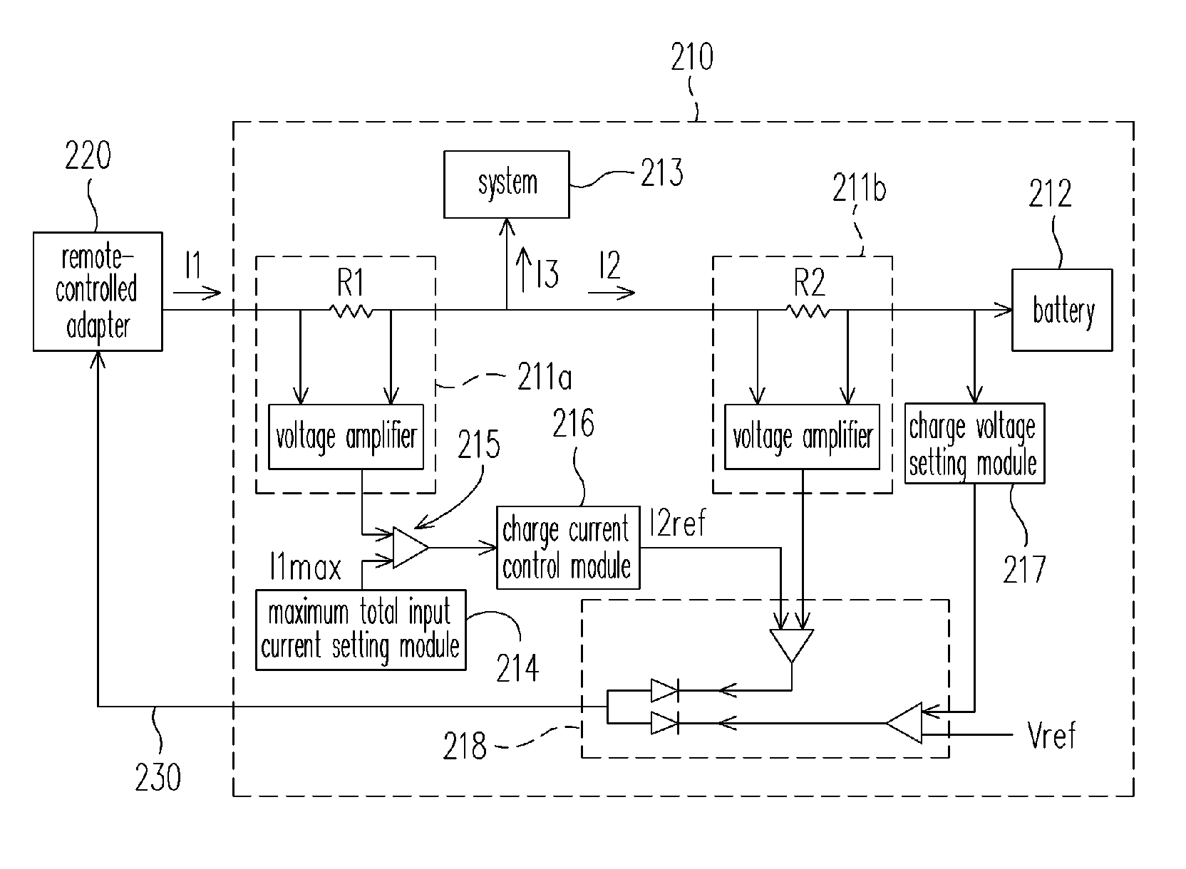
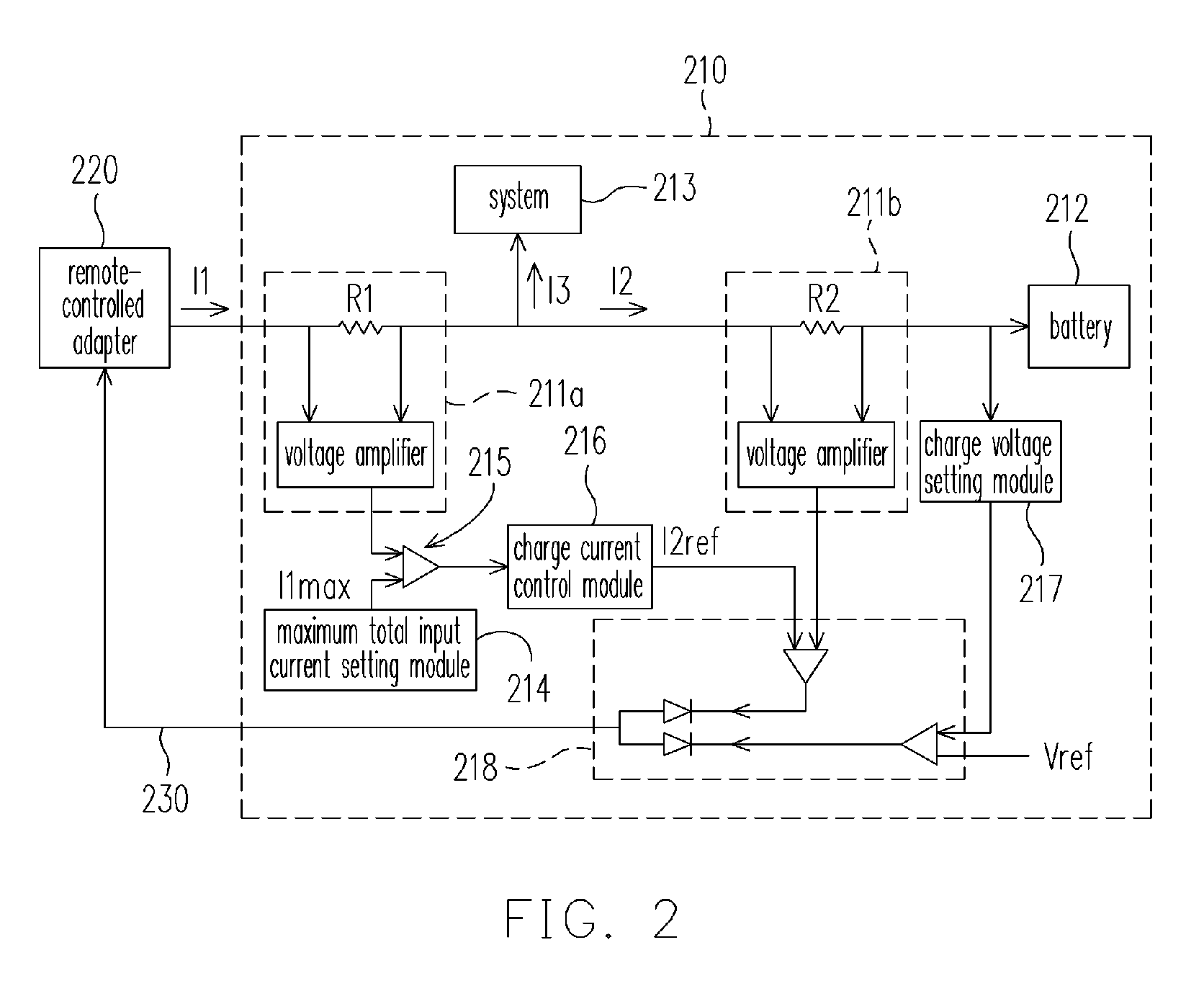
[0021]FIG. 2 is a power control apparatus according to the embodiment of the present invention, wherein in addition to a battery 212 and a system 213, the electronic device 210 further includes: a total input current detecting module 211a, a charge current detecting module 211b, a maximum total input current setting module 214, an amplifier 215, a charge current control module 216, a charge voltage setting module 217, and a feedback signal control module 218, etc. The current output from a remote-controlled adapter 220 is respectively supplied to the battery 212 and the system 213. Wherein, the current output from the output end of the remote-controlled adapter 220 sequentially passes through the current detecting module 211a, the amplifier 215, and the charge current control module 216, and then is input to the feedback signal control module 218. On the other hand, the current output from another output end of the current detecting module 211a passes through the charge current dete...


PUM


Abstract

A power control apparatus and method for an electronic device is provided, which utilizes a charge current control module and a feedback signal control module to transfer the power control signal to a remote-controlled adapter through a feedback circuit, to control the output voltage of the remote-controlled adapter so as to adjust the charge current until the total input current supplied by the remote-controlled adapter is equal to the highest total input current. Therefore, the system of the electronic device can be provided with sufficient power to process needed procedures in a safe condition. Besides, according to the power required by the system of the electronic device, the controller can distribute the power for both the system and the battery in order to improve the efficiency of power use.

Description

CROSS-REFERENCE TO RELATED APPLICATION[0001]This application claims the priority benefit of Taiwan application serial no. 94116837, filed on May 24, 2005. All disclosure of the Taiwan application is incorporated herein by reference.BACKGROUND OF THE INVENTION[0002]1. Field of the Invention[0003]The present invention relates to a power control method, more specifically, to a method of controlling the voltage of the supplying power of the transformer utilizing the feedback signal, for efficient distribution of power use.[0004]2. Description of the Related Art[0005]At present, the power of portable electronic apparatus all relies on the external power supply connected to the electronic device. The method of power supply is to use the charge controller inside the portable electronic device to transfer the power information to the controller in the adapter connected to the portable electronic device, so that the adapter can provide the battery with appropriate charge voltage or charge cu...

Claims


Application Information

Patent Timeline
Patent Type & Authority Patents(United States)
IPC IPC(8): H02J7/02H02J7/00
CPCH02J7/02H02J7/0068H02J5/00
Inventor CHUANG, CHIH-TARNGWU, JENG-JYELU, SHIH-CHINCHEN, CHIEN-HUALEE, LI-JEN
Owner COMPAL ELECTRONICS INC
Learn More