
Dual-path clocking architecture

a clocking architecture and dual-path technology, applied in the direction of generating/distributing signals, pulse automatic control, instruments, etc., can solve the problems of jitter, noise, and noise of on-die clock trees, such as those that are integrated onto the die of an integrated circuit, and achieve the effect of clocks, and reducing the number of clocks

Inactive Publication Date: 2010-04-06
INTEL CORP
View PDF6 Cites 5 Cited by
  • Summary
  • Abstract
  • Description
  • Claims
  • Application Information

AI Technical Summary

Benefits of technology

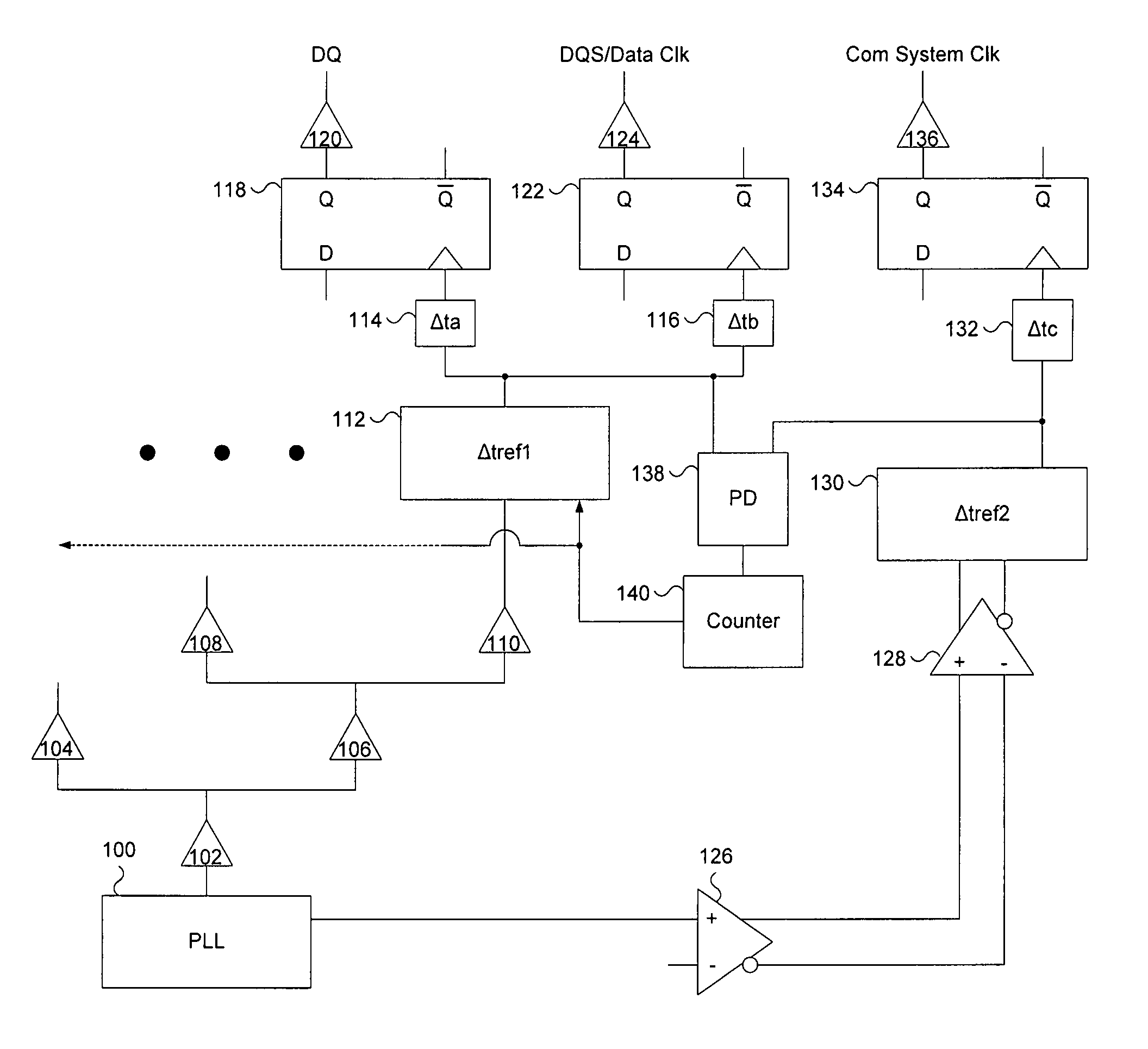
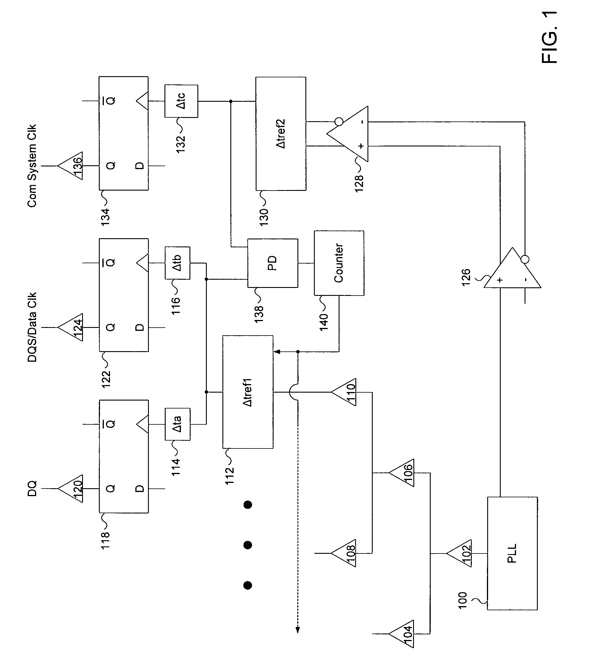
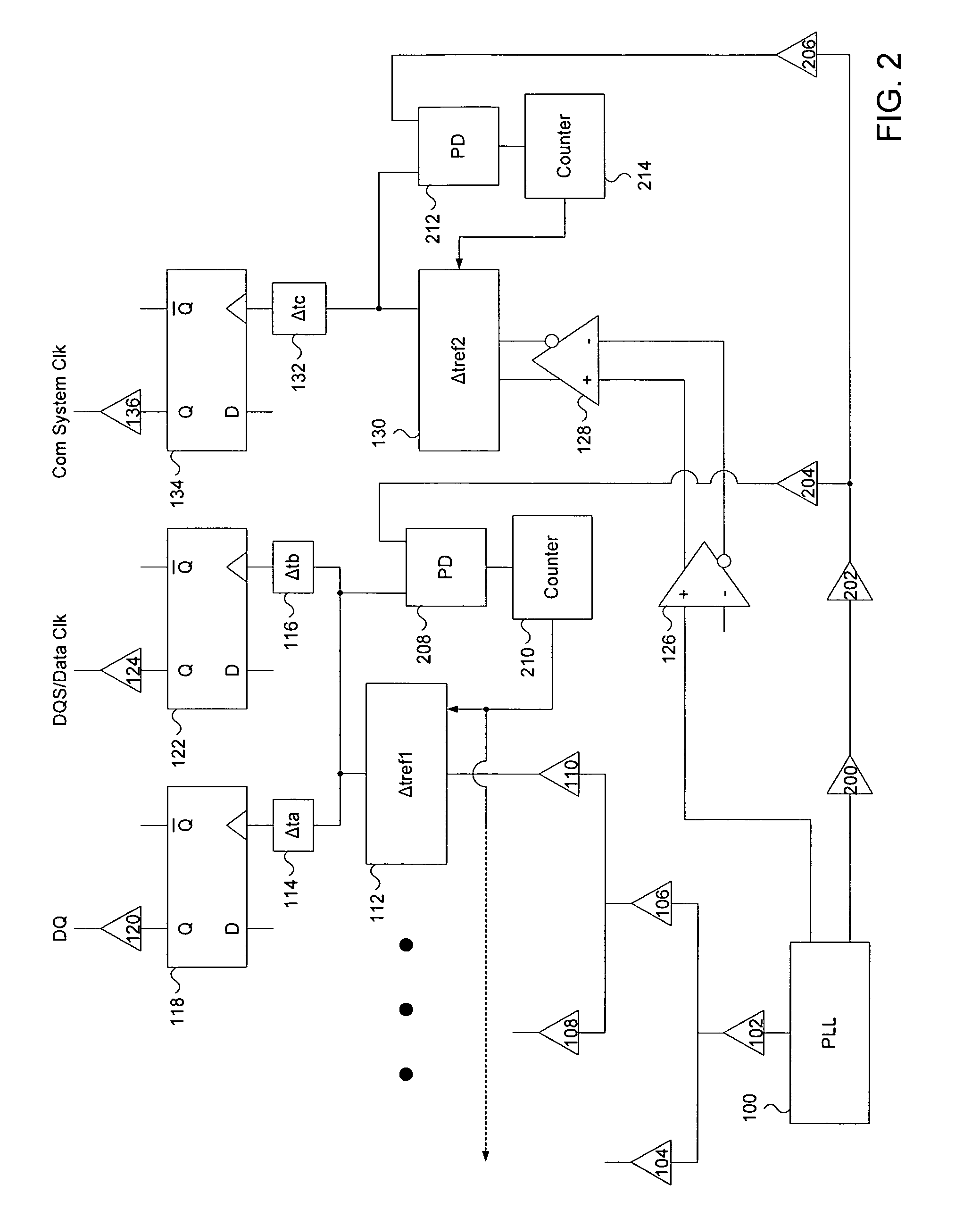
The invention is about a way to save power in clock trees in integrated circuits. Clock trees consume a lot of power and cause jitter (noise) in the clock signal. The invention proposes a dual-path clocking architecture that includes a high-jitter clock tree and a low-jitter clock tree. The high-jitter clock tree uses standard CMOS drivers and is powered at a low operational voltage, which causes significant jitter in the clock signal. The low-jitter clock tree is designed to meet the requirements of the circuitry beyond the drop off points of the clock tree. The invention helps to save power and reduce jitter in the clock signal.

Problems solved by technology

On-die clock trees, such as those that are integrated onto the die of an integrated circuit, consume a significant amount of power.
Each driver introduces a certain amount of noise (i.e. jitter) into the clock signal.
Alternatively, if the circuit does not have strict requirements on the preciseness of the clock signal, the clock tree drivers may be supplied with less power, which would save on power consumption but would cause greater jitter in the clock signal.
Current clock trees are uniformly distributed to all drop off points, although this sometimes requires unnecessary power consumption because different circuitry beyond the different drop off points do not necessarily require the same level of precision (i.e. lack of jitter) of the clock signal.
Thus, tradeoffs exist when deciding whether to implement a lower or higher performance clock tree.

Method used


Image

  • Dual-path clocking architecture
  • Dual-path clocking architecture
  • Dual-path clocking architecture

Examples


Embodiment Construction

[0011]Embodiments of a method and device to provide a dual-path clocking architecture are disclosed. Reference in the following description and claims to “one embodiment” or “an embodiment” of the disclosed techniques means that a particular feature, structure, or characteristic described in connection with the embodiment is included in at least one embodiment of the disclosed techniques. Thus, the appearances of the phrase “in one embodiment” appearing in various places throughout the specification are not necessarily all referring to the same embodiment.

[0012]In the following description and claims, the terms “include” and “comprise,” along with their derivatives, may be used, and are intended to be treated as synonyms for each other. In addition, in the following description and claims, the terms “coupled” and “connected,” along with their derivatives may be used. It should be understood that these terms are not intended as synonyms for each other. Rather, in particular embodimen...


PUM


Abstract

A method and device are disclosed. In one embodiment the method includes driving a first clock domain reference signal on a first clock tree and driving a second clock domain reference signal on a second clock tree. The first tree routes the first signal from a PLL to a first clock domain drop off circuit and the second tree routes the second signal from the PLL to a second clock domain drop off circuit. A jitter produced from the second tree is less than a jitter produced from the first tree. The method continues by detecting any phase misalignment between the first signal and the second signal. The method also causes the first signal to be delayed so that it aligns with the second signal.

Description

FIELD OF THE INVENTION[0001]The invention relates to a dual-path clocking architecture for low power consumption.BACKGROUND OF THE INVENTION[0002]On-die clock trees, such as those that are integrated onto the die of an integrated circuit, consume a significant amount of power. Power consumption has become a very important concern in integrated circuit design considerations. Thus, saving power consumption on the clock tree is one area of that modern integrated circuit designs can benefit from.[0003]Normally, a standard CMOS (complementary metal-oxide semiconductor) clock tree is extended out to a number of clock tree drop off points that each consist of the end of a branch of the tree. The tree is uniformly distributed with drivers (i.e. buffers) to drive the clock signal equally across the tree to all drop off points. Each driver introduces a certain amount of noise (i.e. jitter) into the clock signal. As the clock signal travels through more drivers in a deep clock tree, the jitter...

Claims


Application Information

Patent Timeline
Patent Type & Authority Patents(United States)
IPC IPC(8): H03L7/00
CPCG06F1/10
Inventor TO, HING Y.CHENG, ROGER K.
Owner INTEL CORP
Learn More