
Handoff control method and mobile station

a control method and mobile station technology, applied in the direction of wireless commuication services, broadcast service distribution, electrical equipment, etc., can solve the problems of frequent idle handoff, power consumption, and inability to continue reception, and achieve the effect of improving user-friendliness

Inactive Publication Date: 2010-04-06
LENOVO INNOVATIONS LTD HONG KONG
View PDF9 Cites 8 Cited by
  • Summary
  • Abstract
  • Description
  • Claims
  • Application Information

AI Technical Summary

Benefits of technology

[0016]The object of the present invention is to provide a handoff control method and a mobile station which can enhance user-friendliness when receiving multicast contents.
[0029]According to the present invention, advantages can be attained, wherein idle handoff can reduce instances wherein the reception of multicast content cannot be continued and user-friendliness when receiving multicast content can be enhanced.

Problems solved by technology

However, although, on one hand, the idle handoff plays a part in actualizing a favorable incoming rate by actively catching pilot signals with high pilot strengths, there is a problem in that performing frequent idle handoff is not desirable from the point of view of power consumption.
Therefore, a method is proposed for controlling the increase in idle handoff frequency due to sudden fluctuations in the electromagnetic wave environment by enabling adjustment according to the pilot signal strength (for example, refer to Japanese Patent Laid-open Publication 11-113042) or by implementing, not the instantaneous value of the pilot signal pilot strength, but the temporal average value (for example, refer to Japanese Patent Laid-open Publication 6-335051) However, actively catching pilot signals with high pilot strengths is not necessarily preferable while using multicast service because the multicast contents distributed to each cell differ.
If idle handoff is performed to the second cell, the multicast contents are not distributed in the second cell, and therefore, the reception cannot be continued.

Method used


Image

  • Handoff control method and mobile station
  • Handoff control method and mobile station
  • Handoff control method and mobile station

Examples


first embodiment

A. First Embodiment

[0053]A-1 Configuration of the First Embodiment

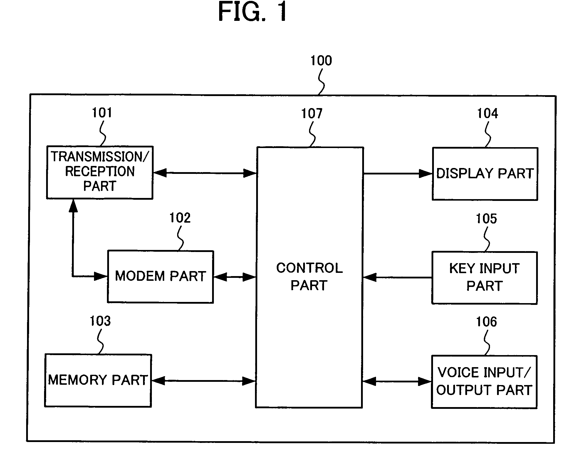
[0054]FIG. 1 is a block diagram showing a configuration of the mobile station according to a first embodiment of the present invention. In this diagram, the mobile station 100 comprises a transmission / reception part 101, a modem part 102, a memory part 103, a display part 104, a key input part 105, a voice input / output part 106, and a control part 107. The transmission / reception part 101 performs transmission and reception of wireless signals. In addition, the transmission / reception part 101 measures the pilot strength of signals received from a wireless base station, particularly the strength of pilot signals. The modem part 102 performs modulation / demodulation of received / transmitted data. The memory part 103 stores programs, voices, images, mail, web, and other user data. The memory part 103 can be either memory embedded within a communication terminal or an external memory, such as a removable memory card.

[0055]Di...

second embodiment

B. Second Embodiment

[0075]Next, a second embodiment of the present invention is explained. The configuration of the mobile station 10 is the same as that in FIG. 1 and, therefore, explanation thereof is omitted. FIG. 6 is a flowchart for explaining the process for adding the base station, of which the pilot strength has risen, as the base station (referred to as the Candidate Set) which becomes a candidate for the idle handoff destination, in the idle handoff control method according to the second embodiment. The operations for each step are explained below.

[0076]First, the control part 107 measures the strength of the pilot signal via the transmission / reception part 101 (step S30). This pilot strength is A. The pilot signal stated herein refers to pilot signals excluding those transmitted by the base station the mobile station 100 is awaiting and pilot signals transmitted by the base stations, out of the other base stations, which are idle handoff destination candidates. If there i...

third embodiment

C. Third Embodiment

[0084]Next, a third embodiment of the present invention is explained. The configuration of the mobile station 100 is the same as that in FIG. 1 and, therefore, explanation thereof is omitted. FIG. 7 is a flowchart for explaining the process for deleting the base station, of which the pilot strength has fallen, from the base station (Candidate Set) which becomes a candidate for the idle handoff destination, in the idle handoff control method according to the third embodiment. The operations for each step are explained below.

[0085]First, the control part 107 measures the strength of the pilot signal via the transmission / reception part 101 (step S50). This pilot strength is A. The pilot signal stated herein refers to one pilot signal out of those transmitted by the base stations which are idle handoff destination candidates of the mobile station 100. If there is a plurality of pilot signals which satisfy this condition, this sequence can be repeated the same number o...


PUM


Abstract

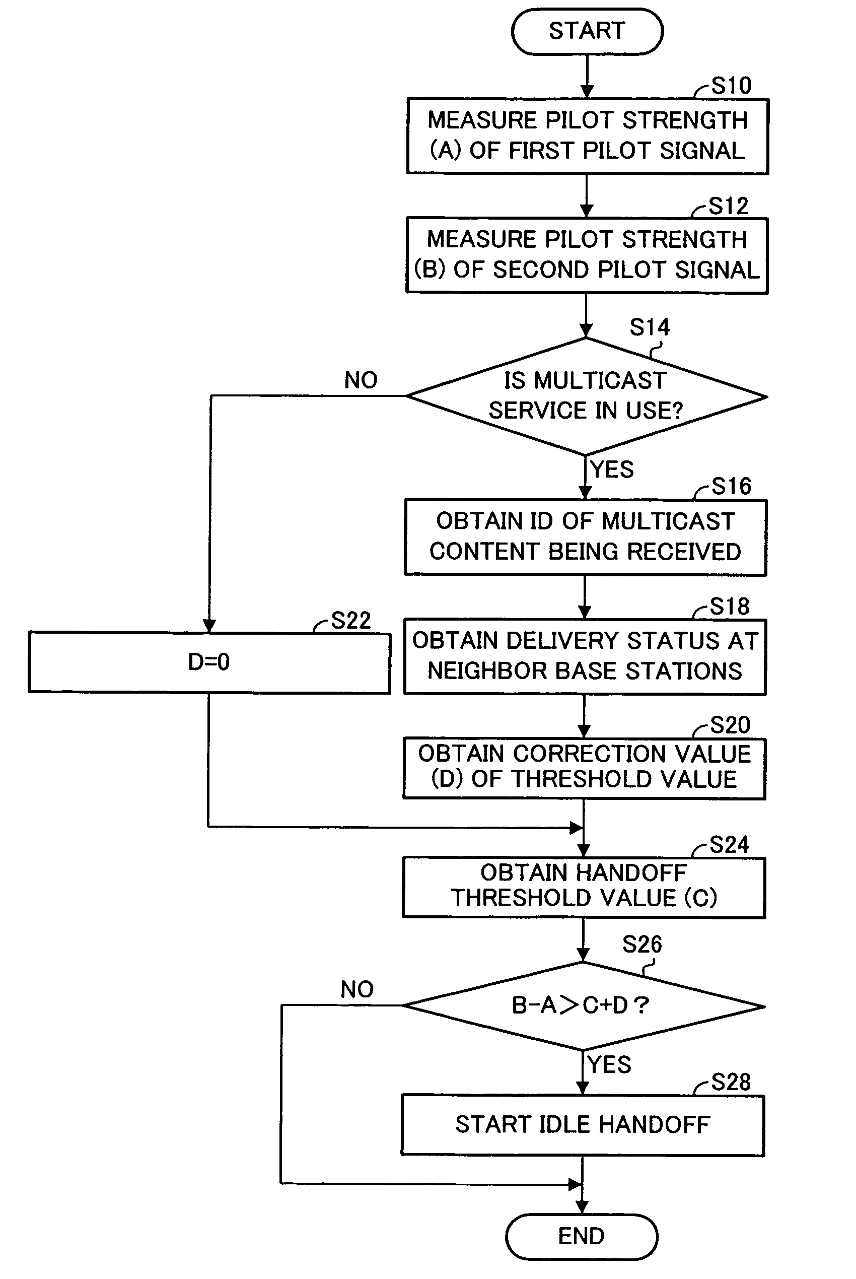
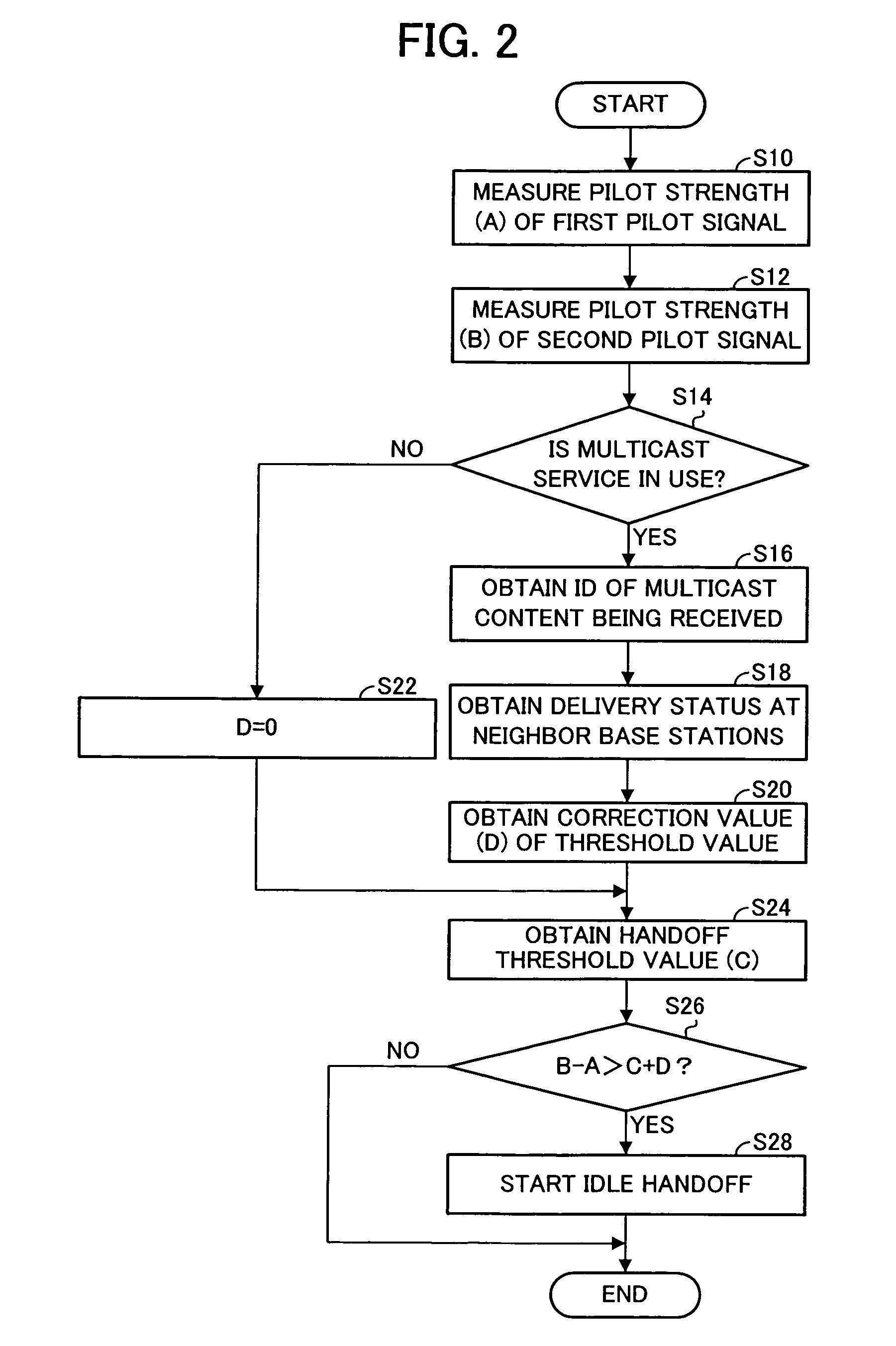
First, the strength A of a first pilot signal currently transmitted by a base station and strength B of a second pilot signal transmitted by a base station other than the foregoing base station are measured, the correction value D of a handoff threshold value according to the multicast service availability and radio configuration information of the multicast content is obtained, and handoff threshold value C is obtained, as well. Next, if the difference between the strength B of the second pilot signal and the strength A of the first pilot signal is greater than the sum of the handoff threshold value C and the correction value D, the idle handoff is started. Through this, idle handoff to neighbor base stations delivering the same multicast content is facilitated and idle handoff to other base stations is made difficult.

Description

CROSS-REFERENCE TO RELATED APPLICATION[0001]This application is based upon and claims the benefit of priority from the prior Japanese Patent Application No. 2004-339828, filed Nov. 25, 2004, the entire contents of which is incorporated herein by reference.BACKGROUND OF THE INVENTION[0002]1. Field of the Invention[0003]The present invention relates to a handoff control method in a mobile communication system and a mobile station implementing thereof.[0004]2. Description of the Related Art[0005]In recent years, services which distribute, through distribution to a plurality of users, contents such as images and voices via a wired broadband line, such as ADSL and FTTH, are becoming increasingly popular. IP multicast technology, represented by Internet Group Management Protocol (IGMP), has implemented such a multicast service.[0006]On the other hand, with the diffusion and sophistication of mobile phones, expectations for wireless multicast service provisions are rising. Specific methods...

Claims


Application Information

Patent Timeline
Patent Type & Authority Patents(United States)
IPC IPC(8): H04W36/00H04W4/06H04W36/30
CPCH04W36/30H04W4/06H04W36/0007
Inventor MIYATA, KATSUYA
Owner LENOVO INNOVATIONS LTD HONG KONG
Learn More