Sheet fastening apparatus and method

a technology of fastening apparatus and sheet metal, which is applied in the direction of couplings, manufacturing tools, shaping tools, etc., can solve the problems of reducing affecting so as to reduce the cost of manufacturing, improve the quality of the product, and improve the effect of joint quality

Inactive Publication Date: 2010-04-13
BTM COMPANY
View PDF47 Cites 40 Cited by
  • Summary
  • Abstract
  • Description
  • Claims
  • Application Information

AI Technical Summary

Benefits of technology

[0006]The present invention is advantageous over prior constructions since the present invention improves joint quality by minimizing overly deep drawing of soft material workpieces, such as aluminum sheets. Thus, joint tearing or cracking is reduced. The present invention is further advantageous since the die assembly is less expensive to manufacture, simple to assemble, and more durable, robust and protected in use than many traditional devices. Moreover, the present invention apparatus advantageously allows joining of three or more material sheets. The apparatus of the present invention is ideally suited for joining together aluminum / polymer / aluminum composite panels used to reduce noise. Additional advantages and features of the present invention will become apparent from the following description and appended claims, taken in conjunction with the accompanying drawings.BRIEF DESCRIPTION OF THE DRAWINGS

Problems solved by technology

Many of these traditional joints, however, have typically required shearing of the sheet material.
Thus, these joints tend to leak rain water and also have their corrosion resistant coatings destroyed.
This traditional construction, however, leaves the moving die components fully exposed to the harsh environment of a typical manufacturing plant such that the die segments appear to be susceptible to falling off of the die, and the spring interfaces to the die segments and screws may be worn or deformed over time through inadvertent workpiece contact or die vibration.

Method used


Image

  • Sheet fastening apparatus and method
  • Sheet fastening apparatus and method
  • Sheet fastening apparatus and method

Examples


Embodiment Construction

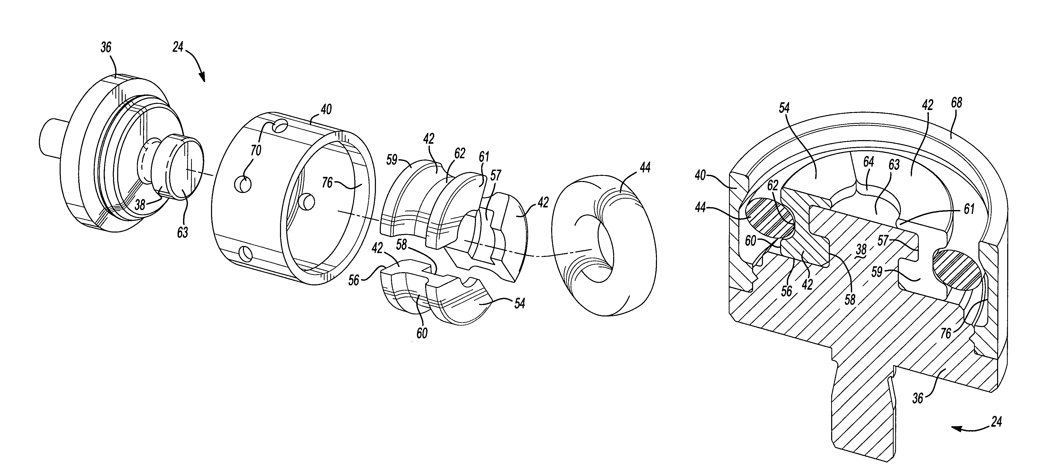
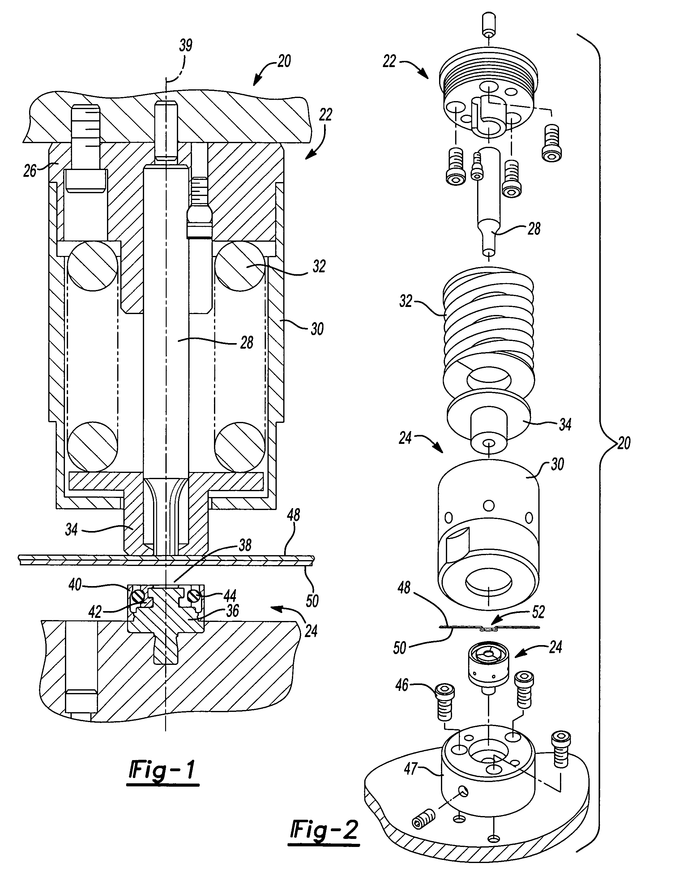
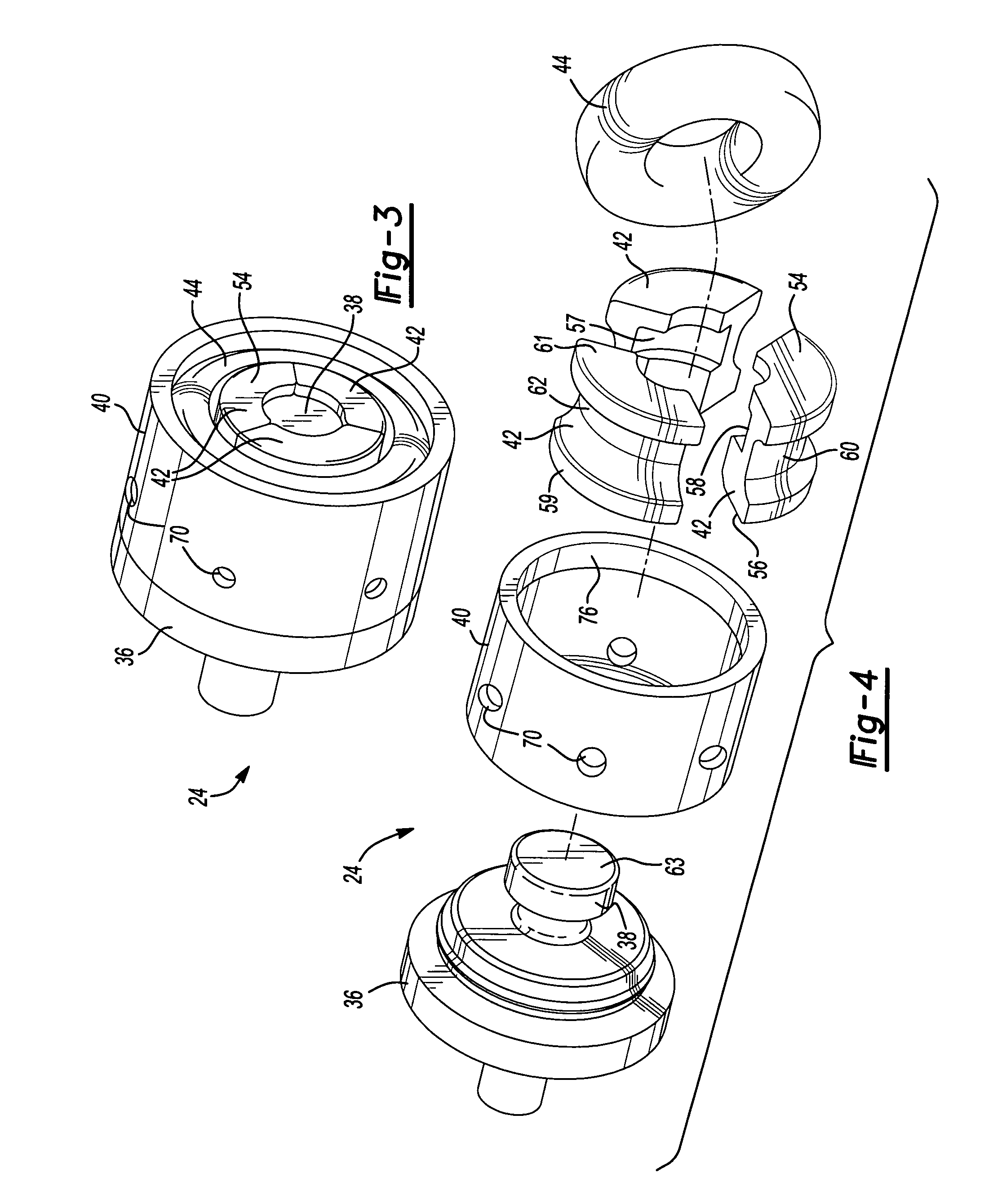
[0019]Referring to FIGS. 1 and 2, the preferred embodiment fastening tool assembly 20 of the present invention employs a punch assembly 22 and a die assembly 24. Punch assembly 22 is pneumatically driven and made in accordance with U.S. Pat. No. 5,727,302. Punch assembly 22 includes a punch holder 26, a punch 28, a housing 30, a compression spring 32 and a stripper 34. Aligned therewith, the preferred die assembly 24 includes a die body 36 having a stationary anvil 38, with a longitudinal axis 39, a shield or guard 40, three movable die blades 42, a flexible retainer 44, mechanical fasteners, such as bolts 46, and a die holder 47. Two or three sheets of workpiece material 48 and 50, such as aluminum, are deformed between punch assembly 22 and die assembly 24 so as to create an interlocking clinch joint 52, which is preferably a leak proof joint.

[0020]Referring to FIG. 3-8, each die blade 42 has axially opposite upper and lower surfaces 54 and 56, respectively, and radially opposite ...


PUM

PropertyMeasurementUnit
shapeaaaaaaaaaa
rounded shapeaaaaaaaaaa
I-cross sectional shapeaaaaaaaaaa

Abstract

A sheet fastening apparatus and method are provided. In another aspect of the present invention, a die assembly for forming a joint between sheets of material is disclosed wherein the die assembly includes an anvil, at least one die blade disposed adjacent to and overlapping a punch-side of the anvil, a flexible retainer, and a shield that coaxially and radially surrounds a portion of the anvil and / or die blade.

Description

BACKGROUND AND SUMMARY OF THE INVENTION[0001]The present invention relates generally to fastening apparatuses and more particularly to a fastening apparatus for forming a clinch joint between sheets of material.[0002]It is common within the metal forming industry to join overlapping workpiece sheets by punching or otherwise deforming them to cause an interlocking relationship in a localized area. Many of these traditional joints, however, have typically required shearing of the sheet material. Thus, these joints tend to leak rain water and also have their corrosion resistant coatings destroyed.[0003]More recently, an apparatus has been used for joining two or more sheets of material together by creating a leakproof and secure joint. These improved conventional joints are created by use of a punch acting against an anvil to produce what is known as a TOG-L-LOC® clinch joint therebetween. Such a leakproof joint and tooling are disclosed in U.S. Pat. Nos. 5,267,383 and 5,177,861, both ...

Claims


Application Information

Patent Timeline
Patent Type & Authority Patents(United States)
IPC IPC(8): B23P11/00B21D39/00
CPCB21D39/031Y10T29/5343Y10T29/49936Y10T29/49943Y10T29/53709Y10T29/49915Y10T29/5377Y10T403/4966Y10T29/53996
Inventor SAWDON, EDWIN GSPROTBERRY, STEVEN J
Owner BTM COMPANY
Why Eureka
Try Eureka