Laundry drier

a technology for laundry driers and dryers, applied in the field of dryers, can solve problems such as increasing manufacturing costs, and achieve the effect of simplifying assembly process and reducing manufacturing costs

Inactive Publication Date: 2010-04-13
LG ELECTRONICS INC
View PDF83 Cites 26 Cited by
  • Summary
  • Abstract
  • Description
  • Claims
  • Application Information

AI Technical Summary

Benefits of technology

[0011]An object of the present invention is to provide a laundry drier capable of reducing manufacturing costs by allowing one kind of side cover to be compatibly used as a left side cover or a right side cover.
[0016]According to the present invention, one kind side cover may be simultaneously used for the left and right side cabinets, which reduces manufacturing costs and simplifies an assembly process.

Problems solved by technology

Therefore, since the left and right side covers should be separately manufactured, manufacturing costs increase.

Method used


Image

  • Laundry drier
  • Laundry drier
  • Laundry drier

Examples


Embodiment Construction

[0025]Reference will now be made in detail to the preferred embodiments of the present invention, examples of which are illustrated in the accompanying drawings. However, the present invention should not be construed as being limited to those preferred embodiments set forth herein, and it will be understood by those skilled in the art that addition, modification, and deletion of another element may be made without departing from the spirit and scope of the present invention.

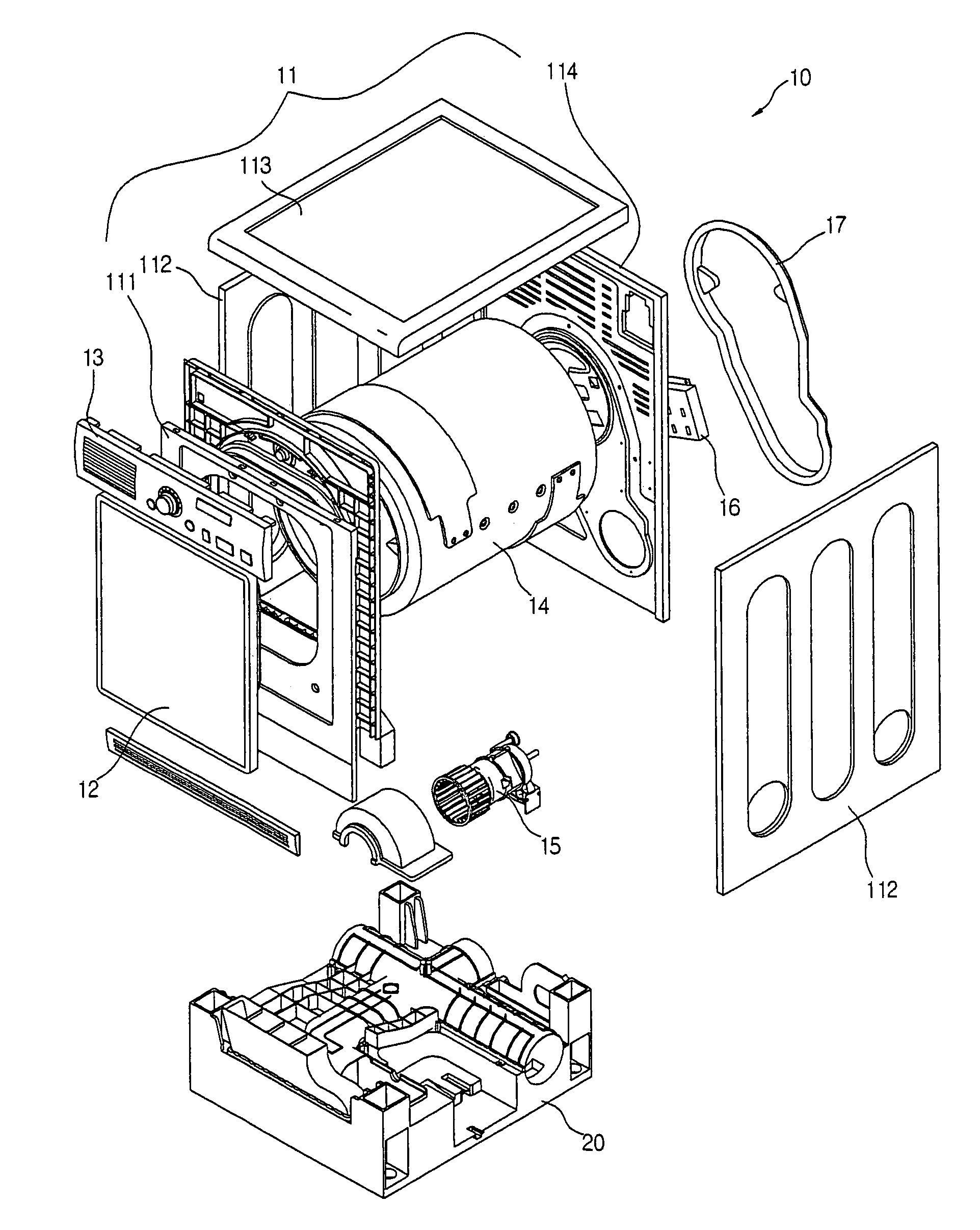
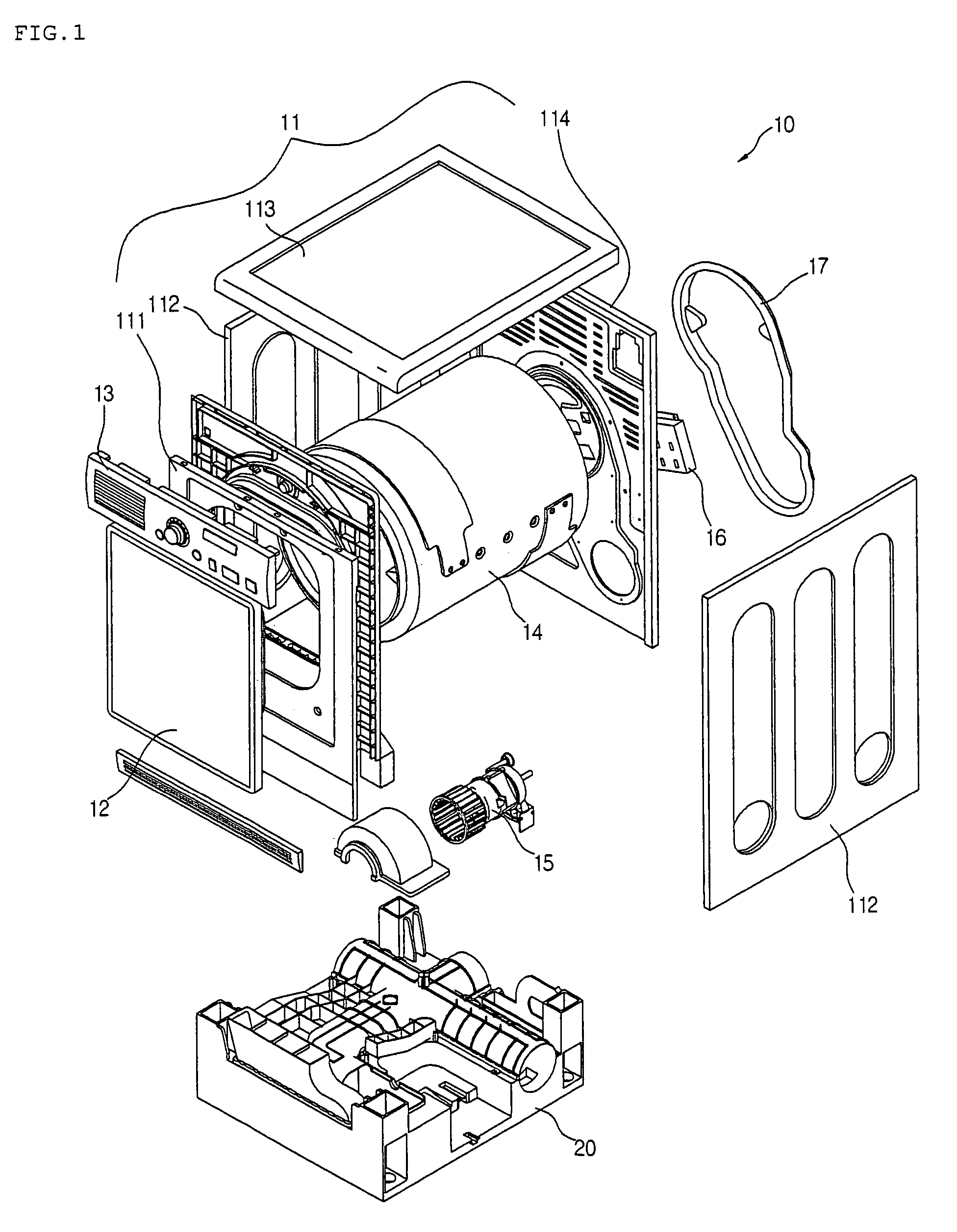
[0026]FIG. 1 is an exploded perspective view of a laundry drier according to the present invention.

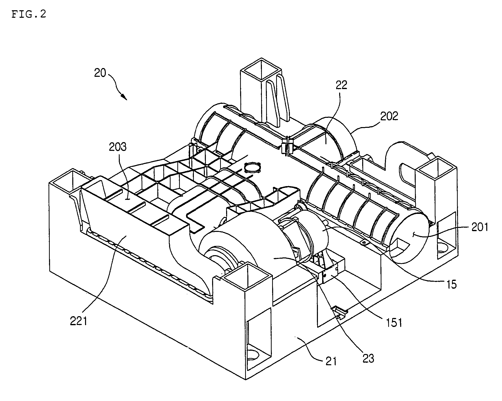
[0027]Referring to FIG. 1, the laundry drier 10 includes: a drying drum 14 for receiving the laundry; a cabinet 11 mounted in the exterior of the drying drum 14 to protect the drying drum 14; a base 20 installed below the drying drum 14 and having an air passage for discharged air formed in the inside of the base; and a motor 15 seated on the base 20 to rotate the drying drum 14.

[0028]In detail, the cabinet 11 inclu...


PUM


Abstract

A laundry drier is provided. The laundry drier includes a base, a drying drum, a front cover, a back cover, a top cover, and side covers. The base includes an air passage in the inside of the base, and at least one discharge port for discharging air that has flowed into the air passage. The drying drum is provided above the base and receives the laundry. The front cover is mounted in front of the drying drum, and the back cover is mounted in the rear side of the drying drum. The top cover is mounted above the drying drum, and the side covers are mounted in the lateral sides of the drying drum and have at least two discharge holes.

Description

BACKGROUND OF THE INVENTION[0001]1. Field of the Invention[0002]The present invention relates to a drier, and more particularly, to a laundry drier capable of reducing manufacturing costs and simplifying an assembling process by allowing one side cabinet to be compatibly used for a left cabinet and a right cabinet, simultaneously.[0003]2. Description of the Related Art[0004]A drum drier is an electronic appliance for receiving wet laundry in the inside of a drying drum and drying the laundry by circulating dry air in the inside of the drying drum.[0005]In detail, the drum dryer is classified into a condensing drier that dries the laundry received in a drying drum by circulating air between the drying drum and a heater, and an exhaust drier where air flows into the drier, and is heated by a heater, flows into a drying drum to dry the laundry, and is then discharged to the outside.[0006]In more detail, in the case of the exhaust drier, air heated while passing through the heater flows...

Claims


Application Information

Patent Timeline
Patent Type & Authority Patents(United States)
IPC IPC(8): F26B11/02
CPCD06F58/20D06F58/04D06F37/26D06F39/12
Inventor LEE, SOON JO
Owner LG ELECTRONICS INC
Why Eureka
Try Eureka