Wind energy plant tower

a technology of wind energy and plant towers, applied in the direction of engine fuctions, structural elements, building components, etc., can solve the problems of high logistic costs, high cost, and significant difficulties in the manufacture and transportation of tower segments, and achieve the effect of high solidity of joints, easy access, and good accessibility

Inactive Publication Date: 2010-04-13
NORDEX ENERGY
View PDF39 Cites 17 Cited by
  • Summary
  • Abstract
  • Description
  • Claims
  • Application Information

AI Technical Summary

Benefits of technology

[0016]After the completion of the tower portion made of the concrete material, the anchor bolts can be fastened, i.e. the connection to the tubular steel-made tower segment needs to be made only when the tower portion made of the concrete material is already completed. In this context, “completed” means that the tower portion made of the concrete material has reached its definite stability and carrying capability, in particular, that the concrete material is completely hardened and that it has optionally be prestressed with a pretension by means of suitable prestressing elements. Thus, the production of the concrete-made tower portion is completely uncoupled from the connection with the steel-made tower segment. In the erection of the wind energy plant tower, this results in the fact that the works on the tower portion made of the concrete material can be completed irrespective of the availability of the steel-made tower segment or of a separate adapter element. Those skilled in the art indebted with the erection of the tower portion made of the concrete material can rapidly complete their work, and the production and supply of the steel-made tower components can optionally take place at a later point in time.
[0033]The method simplifies the erection of a wind energy plant tower, because the tower portion made of a concrete material can be completed before any elements for a steel-made tower portion are needed. Moreover, the installation of the steel-made tower segment with the aid of the anchor bolts is substantially more simple than casting a separate adapter element during the production of the tower portion made of the concrete material. Further advantages of the method have already been explained in the description of the wind energy plant tower to be erected.

Problems solved by technology

From on a certain diameter, significant difficulties in the manufacture and the transportation of the tower segments occur.
This results in a high logistic expense and in high costs.

Method used


Image

  • Wind energy plant tower
  • Wind energy plant tower
  • Wind energy plant tower

Examples


Embodiment Construction

[0037]While this invention may be embodied in many different forms, there are described in detail herein a specific preferred embodiment of the invention. This description is an exemplification of the principles of the invention and is not intended to limit the invention to the particular embodiment illustrated

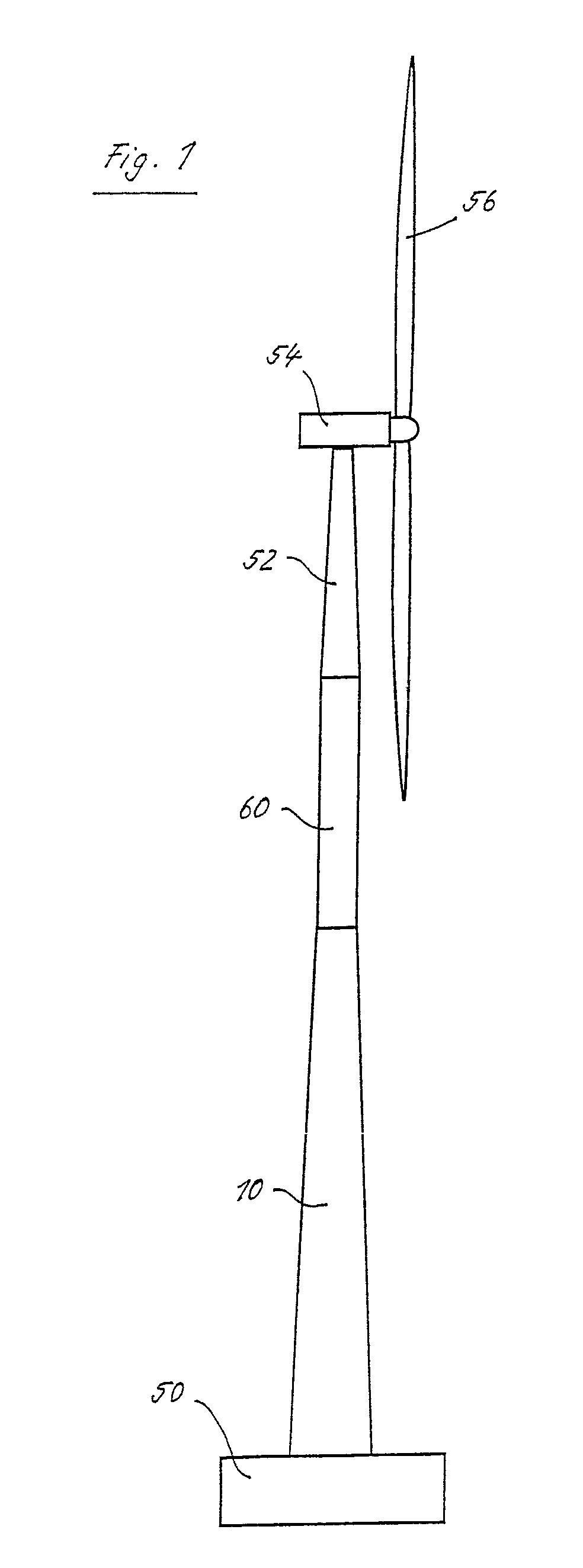
[0038]The wind energy plant depicted in FIG. 1 has a tower portion 10 made of ferroconcrete, which rests on a concrete foundation 50. Above the tower portion 10, there is a tubular steel-made tower segment 60, which is shaped circular cylindrical. A further steel-made tower segment 52 is conical and arranged above the tower segment 60. On its upper end, it has a bearing for the nacelle 54 of the wind energy plant. A rotor 56 with plural rotor blades is rotatably mounted on the nacelle 54. It drives a generator for providing electric power.

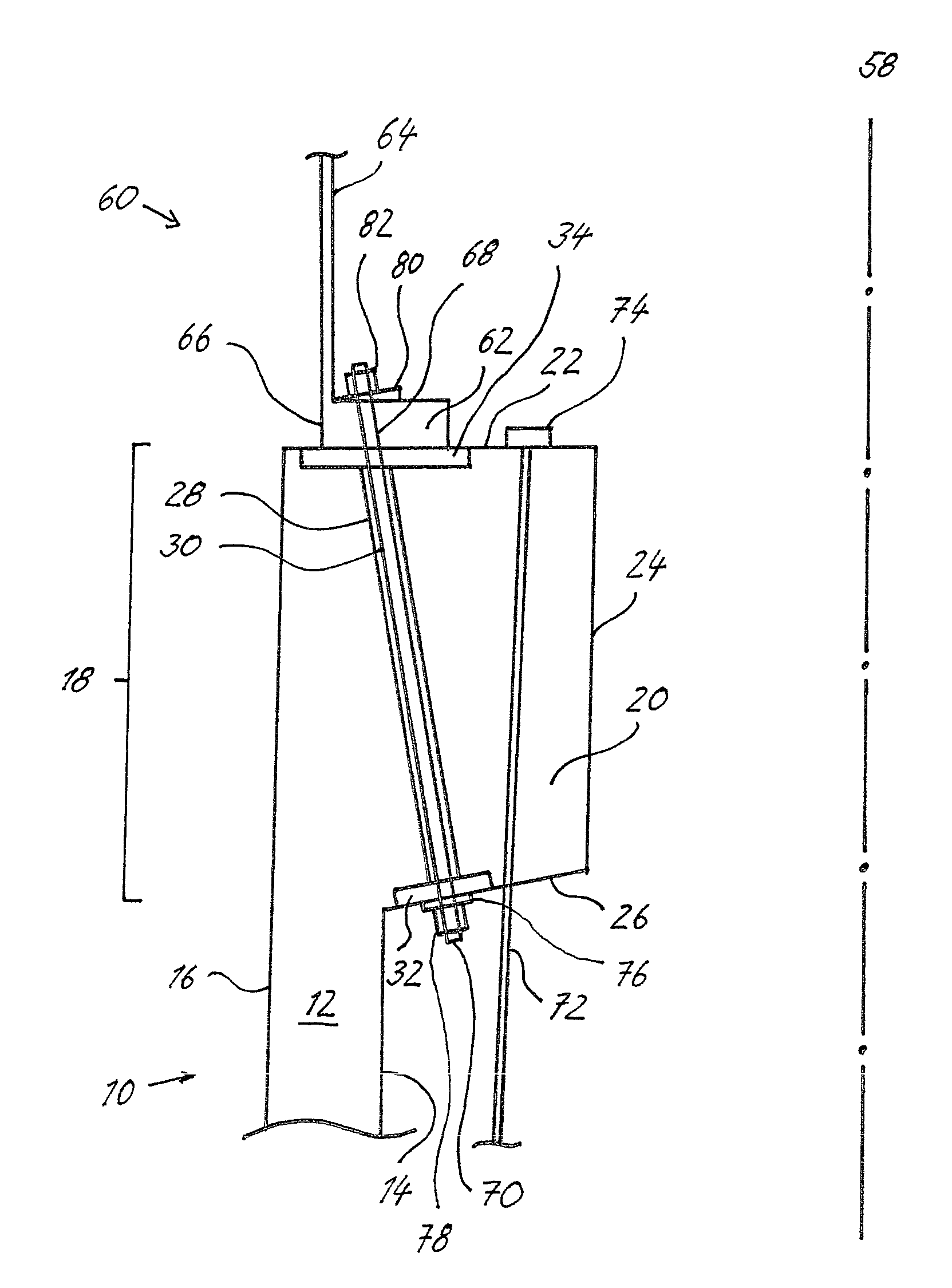
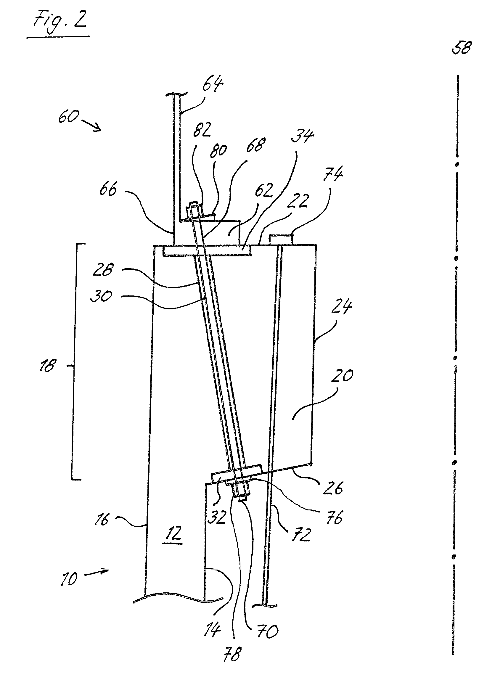
[0039]The cross sectional presentation of FIG. 2 shows a cut-out of the connection location between the steel-made tower segment 60 and the ...


PUM


Abstract

A wind energy plant tower with a tower portion made of a concrete material and a steel-made tubular tower segment, which has on its foot a plurality of connection bores for the connection to the tower portion made of the concrete material, wherein the tower portion made of the concrete material has a head portion with a plurality of openings and a plurality of anchor bolts are provided, which can be fastened after the completion of the tower portion made of the concrete material each at a time in or on one of the connection bores on the foot of the steel-made tower segment and one of the openings in the head portion.

Description

CROSS-REFERENCE TO RELATED APPLICATIONS[0001]Not applicableSTATEMENT REGARDING FEDERALLY SPONSORED RESEARCH[0002]Not applicable.BACKGROUND OF THE INVENTION[0003]The present invention is related to a wind energy plant tower with a tower portion made of a concrete material and a steel-made tubular tower segment, which has on its foot a plurality of connection bores for the connection to the tower portion made of the concrete material.[0004]Wind energy plant towers are frequently made completely from steel, with the exception of a foundation. However, with increasing size of the wind energy plant towers, a very large diameter of the tower is required for sufficient stability, in its lower region in particular. From on a certain diameter, significant difficulties in the manufacture and the transportation of the tower segments occur. This results in a high logistic expense and in high costs.[0005]These difficulties can be avoided by making a lower tower portion from a concrete material. ...

Claims


Application Information

Patent Timeline
Patent Type & Authority Patents(United States)
IPC IPC(8): E04C5/08
CPCE04H12/085E04H12/16F03D11/04Y02E10/728F05B2240/912F05B2260/301F05B2230/60F03D13/20Y02P70/50Y02E10/72
Inventor JAKUBOWSKI, ALEXANDERNITZPON, JOACHIM
Owner NORDEX ENERGY
Why Eureka
Try Eureka