Holding container, external container for kneading and transportation, and kneading device

a technology for kneading and containers, which is applied in the direction of transportation and packaging, rigid containers, rotary stirring mixers, etc., can solve the problems of container damage or destruction, and the following kinds of problems, so as to reduce the burden on the earth environment, reduce the volume of waste, and facilitate the discharging of was

Inactive Publication Date: 2010-04-13
SUNSTAR GIKEN KK +1
View PDF11 Cites 4 Cited by
  • Summary
  • Abstract
  • Description
  • Claims
  • Application Information

AI Technical Summary

Benefits of technology

[0012]According to the container relating to the present invention, since the tubular main body of the container is flexible, after the contents of the container have been used up, the container can be disposed of by crushing the tubular main body, disposing the waste easier and reducing the volume size of the wastes, and thus making it possible to reduce the burden on the earth environment.
[0013]Although a low viscous liquid may also be held in the container, generally the contents of the container are a viscous liquid, such as sealant, adhesive, paint, or the like, formed by a rubber or polymer composition, or a foodstuff, adhesive, shampoo, rinse, hair dressing, beverage, medical liquid, or the like, and regardless of whether or not mixing is required, such liquids can be held, carried out, delivered, transported, stored and mixed in the container.
[0014]According to the external container relating to the present invention, when the container is fitted into the external container, the first engaging projections in the upper end section of the container enter into the engaging recesses, the engaging wall on the outer circumference of the lower end of the container fits into the inner ring groove, the second engaging projections in the circular bottom plate of the external container enter into the engaging holes, and hence the upper end section and the lower end section of the container are engaged in a non-rotatable state with respect to the external container. Therefore, twisting of the tubular main body is reliably prevented during mixing of the contents by rotation of the paddle, and furthermore, rising up of the lower half of the container is also prevented. Consequently, it is possible reliably to prevent the tubular main body of the container from coming into contact with or becoming wound able the paddle, and thus to prevent the container from being damaged or broken.

Problems solved by technology

However, if the aforementioned flexible container is used as a container for holding a sealant, then problems of the following kinds are occurred.
More specifically, if the container for sealant is inserted into an external container for mixing and transportation, this external container is mounted onto and fixed to the agitating platform of a mixing device, and the sealant held in the container for sealant is mixed in a general method, then it is known that problems may occur, namely, that the flexible tubular main body of the container may twist, the lower half section of the container may rises upwards, and the container may be damaged or destroyed due to the container becoming wound about the paddles or coming into contact with the paddles.

Method used


Image

  • Holding container, external container for kneading and transportation, and kneading device
  • Holding container, external container for kneading and transportation, and kneading device
  • Holding container, external container for kneading and transportation, and kneading device

Examples


first embodiment

[0069]Firstly, a first embodiment of the present invention is described with reference to FIG. 1 to FIG. 11.

[0070]Symbol A in the drawings indicates a flexible container made of soft plastic.

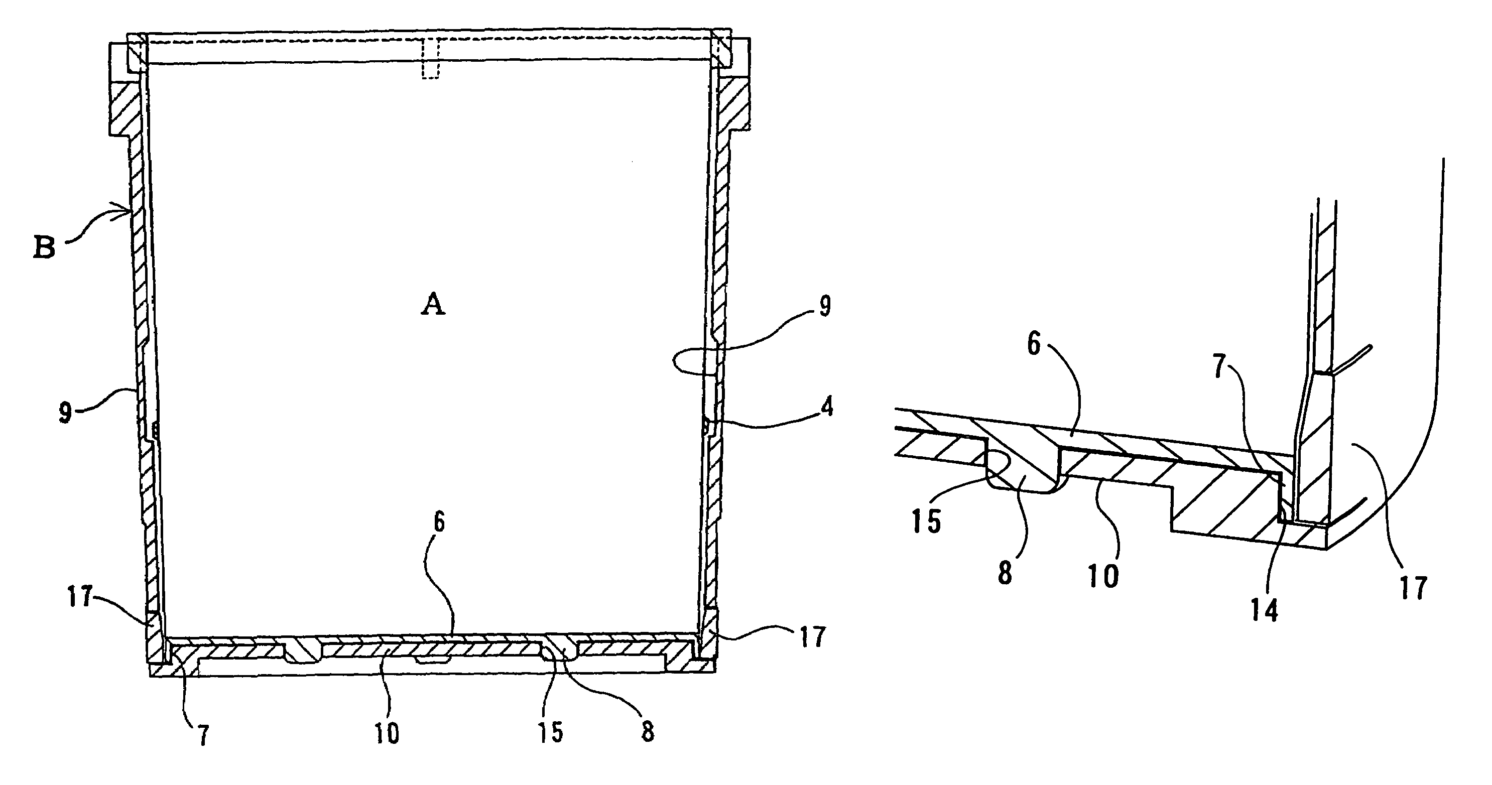
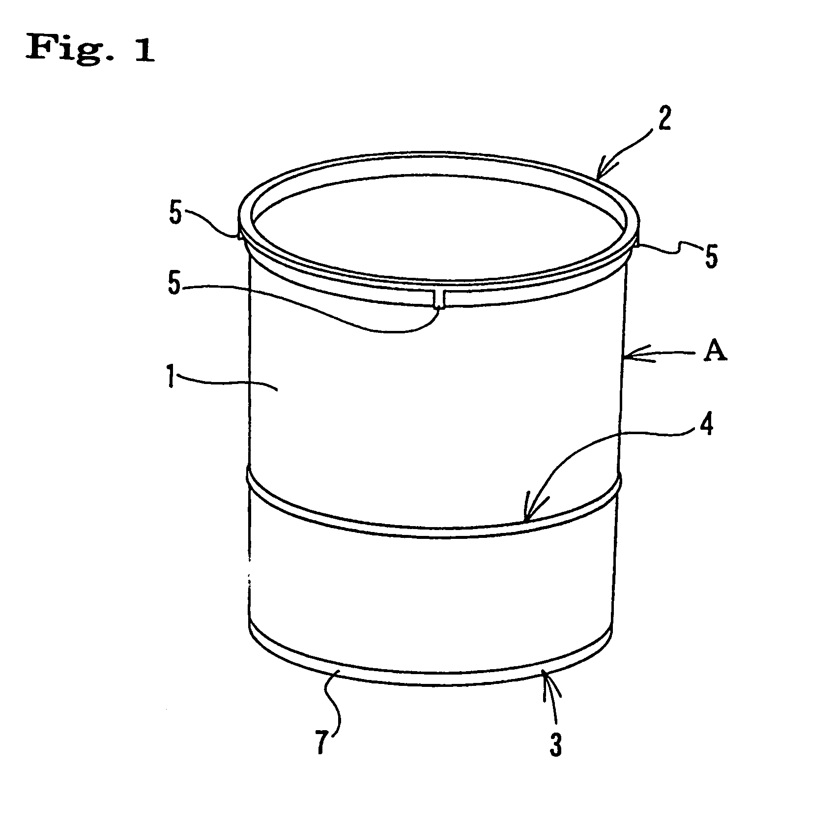
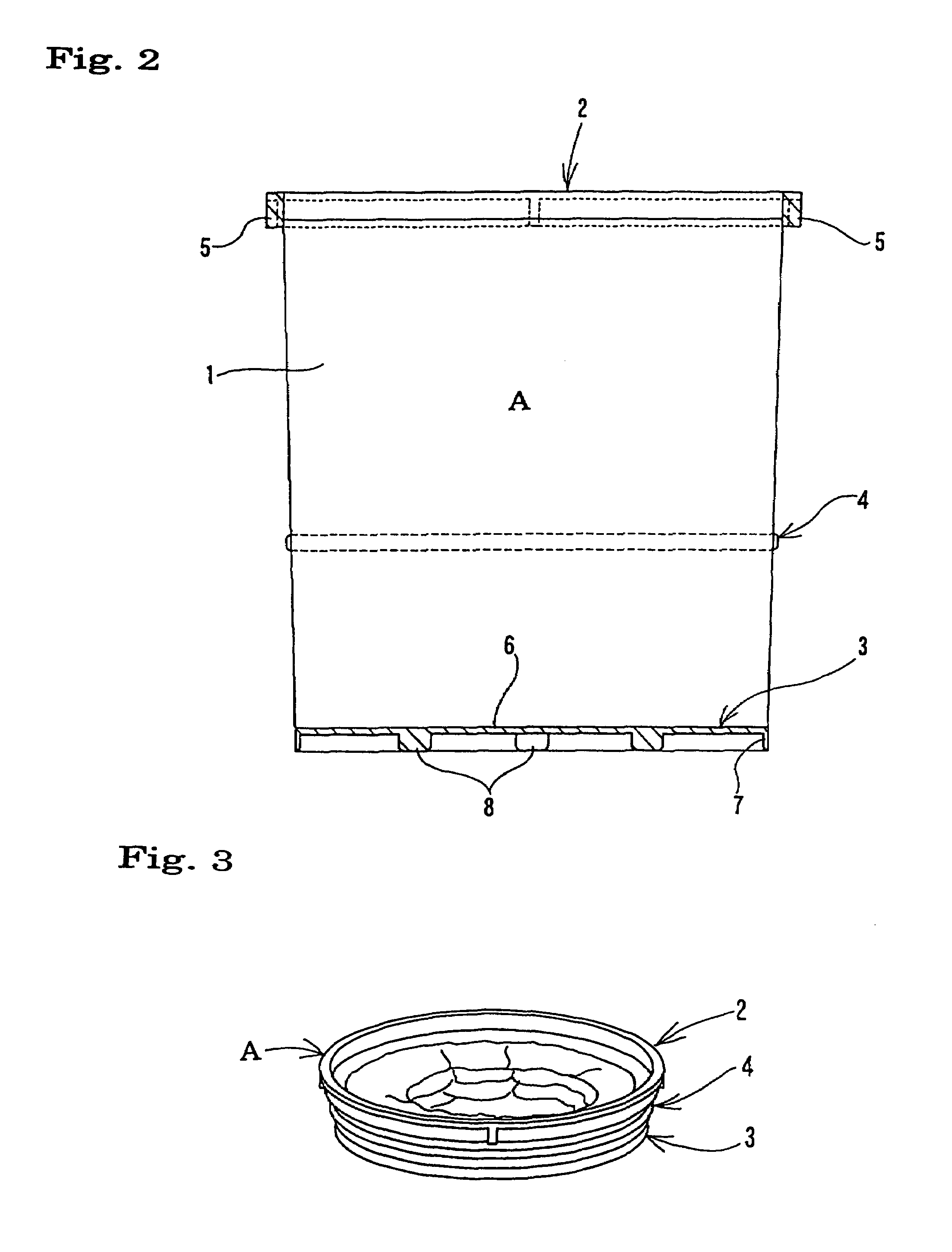
[0071]This container A is formed by fixing a plastic ring-shaped rim frame 2 onto the upper end of a flexible tubular main body 1, which decreases gradually in diameter from the side of the upper end opening thereof towards the lower end opening thereof, and the ring-shaped rim frame 2 and the tubular main body 1 form an integrated body, and furthermore, affixing a plastic bottom plate 3 to the lower end opening and forming at least one ring-shaped trunk section frame 4 having a band-shape, made from plastic, metal, leather, cloth, or the like, on the outer circumferential surface of the tubular main body 1. In the container according to the present embodiment, one plastic ring-shaped trunk section frame 4 is provided integrally with the outer circumferential surface of the tubular main body in ...

second embodiment

[0094]Next, a second embodiment of the present invention will be described in detail with reference to FIGS. 12 to 27.

[0095]Symbol D in the drawings is a flexible container made of soft plastic. This container D comprises a tubular main body 21 of a prescribed plastic laminate film and a plastic ring-shaped rim frame 22 onto the upper end of a tubular main body 21, which decreases gradually in diameter from the upper end opening thereof towards the lower end opening thereof, in such a manner that the ring-shaped rim frame 22 and the tubular main body 21 form an integrated body, in addition to which, a plastic bottom plate 23 is affixed to the lower end opening of the tubular main body 21; and at least one ring-shaped trunk section frame 24 having a band-shape, made from plastic, metal, leather, cloth, or the like, is formed on the outer circumferential surface of the tubular main body 21. In the container according to the present embodiment, one plastic ring-shaped trunk section fra...


PUM


Abstract

In order to achieve a container which is convenient for carrying, delivery, transportation and storage of a viscous liquid, which can be disposed by being crushed to a small volume size when it has become empty, and which prevents twisting or rising up of the lower half of the container during a mixing of a viscous liquid, a container A holding liquid is used, wherein a ring-shaped rim frame 2 is provided on the upper end of a flexible tubular main body 1, a bottom plate 3 is fitted onto an opening at the lower end thereof, and at least one ring-shaped trunk section frame 4 is provided on the outer circumferential surface of said tubular main body 1.

Description

TECHNICAL FIELD[0001]The present invention relates to a container which can be used suitably for carrying, delivery, transportation, mixing, churning and storing a viscous liquid such as a sealant, adhesive, paint material, mortar, concrete, miso paste, mayonnaise type food product, cleaning material, shampoo, rinse, hair dressing, beverage and medical liquid, and to an external container for mixing and transportation which can be fitted onto the container and attached to and detached from an agitating platform of a prescribed mixing device, and to a mixing device for mixing viscous liquid that is filled into the container.BACKGROUND ART[0002]Japanese Patent No. 3289192 discloses: (1) a sealant container which can be inserted into an external container for mixing and transportation of a sealant that is attachable to and detachable from the agitating platform of a mixing device, the sealant container being formed, furthermore, with a rotation preventing engagement section in a requir...

Claims


Application Information

Patent Timeline
Patent Type & Authority Patents(United States)
IPC IPC(8): B01F11/00B65D21/08B65D77/00B65D77/04B65D77/06B65D8/14
CPCB01F7/1605B44D3/12B44D3/08B01F2215/005B01F27/805B01F2101/30
Inventor HATTORI, EIJIMATSUMURA, MASAYOSHISHIMIZU, KAZUHITOOSAKA, TOSHIHARUICHIKAWA, TOORUITO, MASAHIROTANAKA, YOJI
Owner SUNSTAR GIKEN KK
Why Eureka
Try Eureka