Rotor shaft support structure and supercharger

A technology of supporting structure and rotor shaft, which is applied in the direction of rotating bearings, bearings, bearing assembly, etc., can solve the problems of increased wear of setting holes and semi-floating bushings, and it is difficult to improve the durability of superchargers for vehicles. , to achieve the effect of improving the rotation stability

Active Publication Date: 2016-06-15
IHI CORP
View PDF11 Cites 0 Cited by
  • Summary
  • Abstract
  • Description
  • Claims
  • Application Information

AI Technical Summary

Problems solved by technology

On the other hand, if the gap between the inner peripheral surface of the installation hole and the outer peripheral surface of the intermediate bushing is uniformly enlarged, when the force generated by the pressure difference between the compressor impeller and the turbine impeller acts on the oil , worried about causing oil deflector between the inner peripheral surface of the setting hole and the outer peripheral surface of the second bearing part, resulting in increased wear between the setting hole and the semi-floating bushing
[0010] In other words, it is not easy to improve the durability of the vehicle supercharger and to reduce the mechanical loss of the rotor shaft support structure to improve the efficiency of the vehicle supercharger.

Method used


Image

  • Rotor shaft support structure and supercharger
  • Rotor shaft support structure and supercharger
  • Rotor shaft support structure and supercharger

Examples


Embodiment Construction

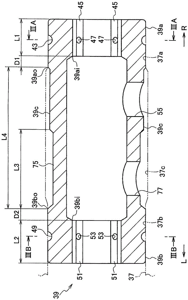
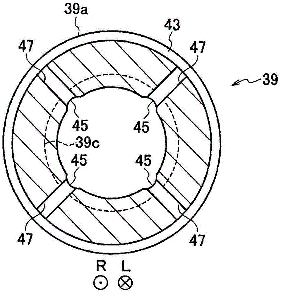
[0023] refer to Figure 1 ~ Figure 4 Embodiments of the present invention will be described. Wherein, as shown in the accompanying drawings, "L" means the left side, and "R" means the right side.

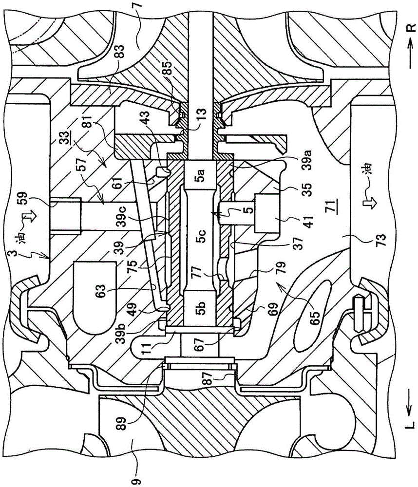
[0024] Such as figure 1 as well as Figure 4 As shown, the vehicle supercharger (an example of a supercharger) 1 according to the embodiment of the present invention supercharges (compresses) the air supplied to the engine by utilizing the pressure energy of the exhaust gas from the engine (not shown). ).

[0025]The vehicle supercharger 1 includes a bearing housing 3 and a rotor shaft (turbine shaft) 5 rotatably provided on the bearing housing 3 and extending in the left-right direction. In addition, a compressor impeller 7 for compressing air by centrifugal force is integrally provided at one end portion (right end portion) of the rotor shaft 5 . The other end (left end) of the rotor shaft 5 is integrally provided with a turbine wheel 9 that generates a rotational force (rota...


PUM


Abstract

The invention provides a rotor shaft supporting structure and a supercharger. The semi-floating bushing includes: a first bearing part, a middle bushing part and a second bearing part. The end edge (39ai) of the inner peripheral surface of the first bearing portion is located closer to the compressor impeller (7) side than the edge (39ao) of the outer peripheral surface of the first bearing portion (39a). The edge (39bi) of the inner peripheral surface of the second bearing portion (39b) is located closer to the turbine impeller (9) side than the edge (39bo) of the outer peripheral surface of the second bearing portion (39b). On the outer peripheral surface of the intermediate bushing portion, except for the portion adjacent to the first bearing portion, a peripheral oil storage groove is formed. An oil discharge hole is formed through a lower portion of the intermediate bushing. An oil discharge passage is formed through the underside of the semi-floating bush in the support seat portion.

Description

technical field [0001] The present invention relates to a rotor shaft support structure of a supercharger mounted on a vehicle or the like, and a supercharger provided with the rotor shaft support structure. Background technique [0002] Generally, a vehicle supercharger includes a bearing housing, and a rotor shaft that is rotatably provided to the bearing housing and integrally couples a compressor impeller and a turbine impeller on the same shaft. In addition, from the viewpoint of reducing the noise of a vehicle supercharger, a rotor shaft support structure equipped with a semi-floating bush (semi-floating bearing) is widely used in a vehicle supercharger (see JP-A 2012- 219788 and Japanese Patent Laid-Open No. 2012-193709). [0003] The structure of a typical rotor shaft support structure will be briefly described. The bearing housing has a bearing seat portion on the inner side. An installation hole is formed through the support seat portion along the axial directio...

Claims


Application Information

Patent Timeline
Patent Type & Authority Patents(China)
IPC IPC(8): F01D25/28F01D25/16
CPCF01D25/166F01D25/18F05D2220/40F05D2260/98F16C2360/24F16C27/02F16C2226/50F16C17/10
Inventor 大谷友美采浦宽大东佑一小岛英之
Owner IHI CORP
Why Eureka
Try Eureka