A kind of exterior wall cleaning robot and cleaning method thereof
An exterior wall cleaning and robot technology, applied in cleaning machinery, machine parts, cleaning equipment, etc., can solve problems such as unfavorable cleaning work and increased difficulty in operation
- Summary
- Abstract
- Description
- Claims
- Application Information
AI Technical Summary
Problems solved by technology
Method used
Image
Examples
Embodiment 1
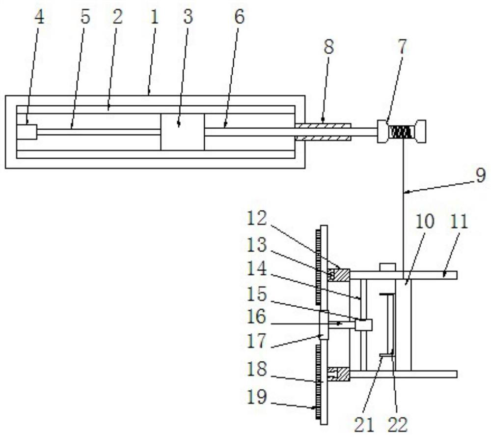
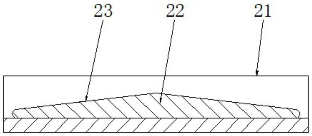
[0030] See Figure 1-2, an exterior wall cleaning robot, including a seat frame 1, the seat frame 1 is a rectangular frame structure, the upper and lower walls of the inner cavity of the seat frame 1 are symmetrically fixed with first slide rails 2, between the two first slide rails 2 Slidingly connected with a lifting motor device 3, the inner cavity left wall of the seat frame 1 is fixedly equipped with an electric telescopic device 4, and the movable end of the telescopic rod 5 on the electric telescopic device 4 is fixedly connected to the lifting motor device 3, so The lifting motor device 3 is rotatably connected with a lifting shaft 6. The overhanging end of the lifting shaft 6 runs through the side wall of the seat frame 1 and is fixedly connected with a hoisting roller 7. The lifting shaft 6 and the seat frame 1 are connected in rotation. , the hoisting roller 7 is wound with a hoisting rope 9, the bottom end of the hoisting rope 9 is fixedly connected with a base fra...
Embodiment 2
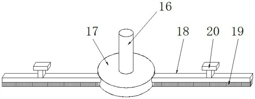
[0033] See image 3 , the difference from Embodiment 1 is: the cleaning mechanism includes a cleaning motor 15, the cleaning motor 15 is arranged between all the fixed rods 11 and close to the side of the second slide rail 12, and the cleaning motor 15 passes through the connecting rod 14 is fixedly connected on the fixed rod 11, and there is a one-to-one relationship between the connecting rod 14 and the fixed rod 11. The cleaning motor 15 is connected with a cleaning rotating shaft 16, and the overhanging end of the cleaning rotating shaft 16 is fixed. A cleaning disc 17 is connected, and the axis of the cleaning rotating shaft 16 coincides with the axis of the cleaning disc 17 and the axis of the second slide rail 12. The cleaning disc 17 is a disc structure. The cleaning brush 18 matched with the second slide rail 12, the cleaning brush 18 is provided with a slide block 20 matched with the chute 13, and the cleaning brush 18 is provided with bristles 19, during cleaning, t...
Embodiment 3
[0035] See Figure 4-5 , and the difference from Embodiment 1 is: a close fan mechanism 24 is provided on the side away from the second slide rail 12 between all the fixed rods 11, and the close fan mechanism 24 includes a frame body 25, the The frame body 25 is a ring structure, and the frame body 25 is fixedly installed between all the fixed rods 11. The inner cavity of the frame body 25 is provided with a propulsion fan 26, and the propulsion fan 26 is fixedly connected to the frame body 25 through the installation rod 27. , start the propulsion fan 26 in the forward direction to generate a forward thrust, and cooperate with the base frame 10 and the fixed rod 11 to further promote the cleaning mechanism to be close to the outer wall to ensure the cleaning quality of the cleaning mechanism on the outer wall; at the same time, start the propulsion fan 26 in the reverse direction, Generate a reverse thrust, and cooperate with the base frame 10 and the fixed rod 11 to reversel...
PUM
 Abstract
Description
Claims
Application Information
 - R&D
- Intellectual Property
- Life Sciences
- Materials
- Tech Scout
- Unparalleled Data Quality
- Higher Quality Content
- 60% Fewer Hallucinations
Browse by: Latest US Patents, China's latest patents, Technical Efficacy Thesaurus, Application Domain, Technology Topic, Popular Technical Reports.
© 2025 PatSnap. All rights reserved.Legal|Privacy policy|Modern Slavery Act Transparency Statement|Sitemap|About US| Contact US: help@patsnap.com


