Storage apparatus, control method, and control device which enable or disable compensation control

a technology of compensation control and storage apparatus, which is applied in the field of storage apparatus, can solve the problems of rotation disturbance vibration, head position error, and affect the accuracy of head positioning, and achieve the effect of preventing the deterioration of head positioning accuracy

Active Publication Date: 2010-04-13
KK TOSHIBA
View PDF24 Cites 7 Cited by
  • Summary
  • Abstract
  • Description
  • Claims
  • Application Information

AI Technical Summary

Benefits of technology

[0010]According to the present invention to provide a storage apparatus, a control method, and a control method which reliably prevent the deterioration of the head positioning accuracy during the following control even when the signals from the acceleration velocity sensor include foreign noise such as power source ripples or noise due to SN of the sensor itself.
[0040]According to the present invention, influence imposed on head positioning control is respectively detected as position errors when compensation control is enabled and disabled, and the compensation control is enabled or disabled corresponding to the smaller one of the position errors. Therefore, when the signal from the acceleration velocity sensors includes rotation disturbance vibration components, the compensation control is enabled so as to enhance the head positioning accuracy. On the other hand, when the signal from the acceleration velocity sensors includes foreign noise such as translation disturbance vibration components or power source ripple, the compensation control is disabled, and the noise components cased by the compensation signal are not applied to the positioning control system. Therefore, deterioration of the head positioning accuracy due to the noise components can be prevented.
[0041]Moreover, also regarding the noise due to the sensor itself caused by the S / N ratio of the acceleration velocity sensor in a normal case in which no translation vibration disturbance and foreign noise is applied, the compensation control is disabled, and deterioration of the head positioning accuracy due to the noise component can be prevented.

Problems solved by technology

However, in a usage environment of the magnetic disk apparatus, it is put in a rack of, for example, a server or a storage system; therefore, it is affected by the vibrations of a fan or another magnetic disk apparatus.
On the other hand, the torsion vibrations are the vibrations that moves the entire apparatus in a rotation direction about a certain position, become the vibrations that moves the rotary actuator rotatably supported by a pivot shaft in the rotation direction, and become disturbance that causes a head position error, which is called rotation disturbance vibrations.
However, in the conventional compensation control using the acceleration velocity sensor, the signals output from the acceleration velocity sensor may include noise components caused by the factors other than the rotation disturbance vibrations such as translation vibrations, power source ripples, and the S / N ratio of the sensor itself in some cases, and there is a problem that the positioning accuracy is deteriorated by the influence of the noise components contained in the compensation signals of the rotation disturbance vibrations added to the positioning control system.
The acceleration velocity sensor used in the compensation control is intended to detect the rotation disturbance vibrations in the disk plane (X-Y plane) of the magnetic disk apparatus; however, in practice, there is a problem that the output of the acceleration velocity sensor includes signal components other than the rotation disturbance vibrations caused by power source ripple noise or translation in the direction (Z direction) orthogonal to the disk plane, appropriate sensor signals are fed forward to the positioning control system as a result, and the head positioning error is worsen.
There is also a problem that the positioning accuracy is worsen when such sensor signal is fed forward to the positioning control system.

Method used


Image

  • Storage apparatus, control method, and control device which enable or disable compensation control
  • Storage apparatus, control method, and control device which enable or disable compensation control
  • Storage apparatus, control method, and control device which enable or disable compensation control

Examples


Embodiment Construction

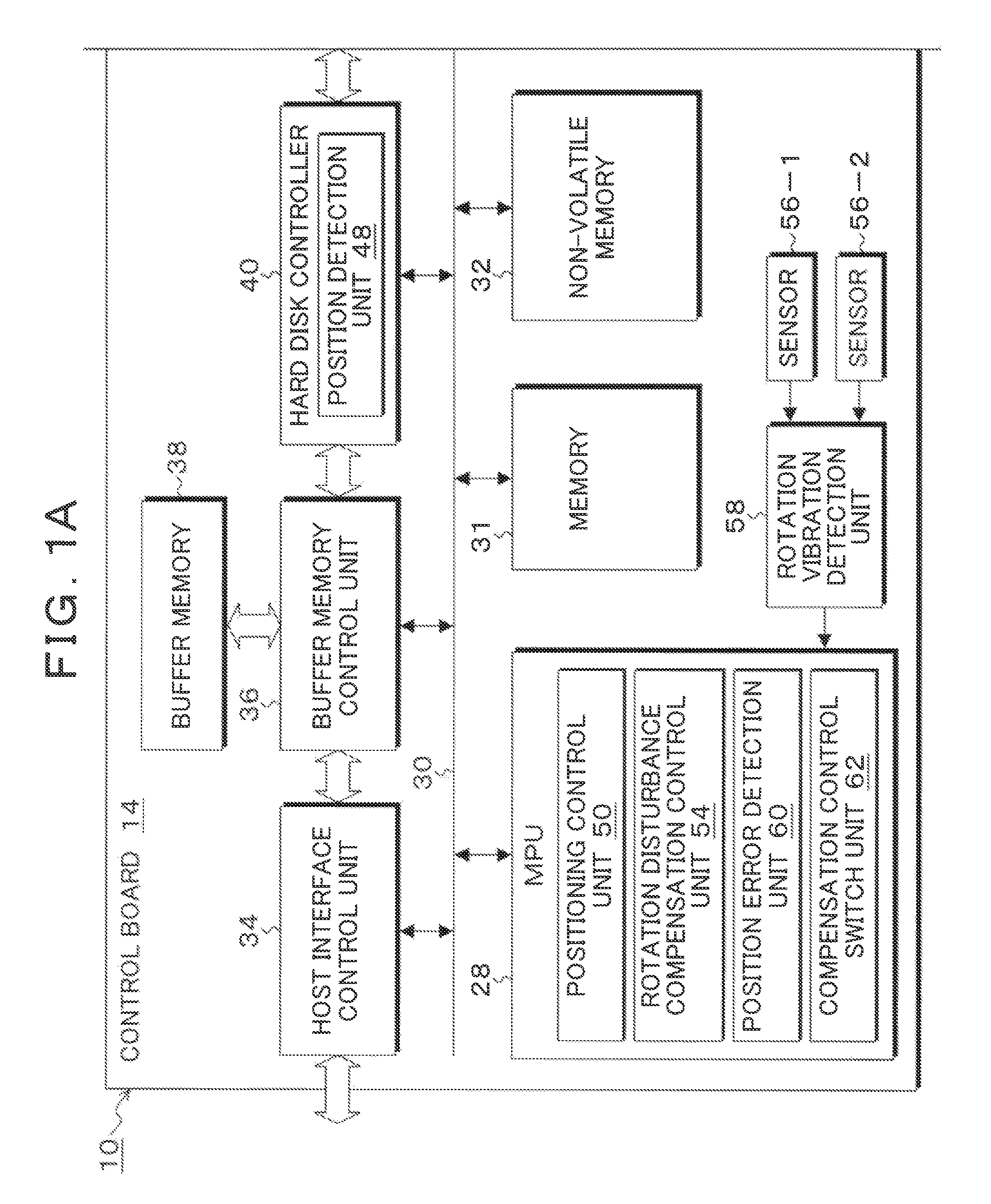
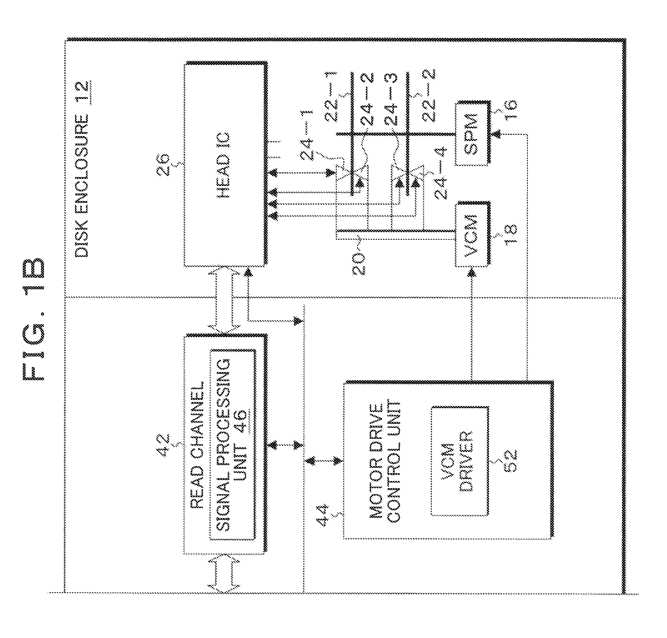
[0057]FIGS. 1A and 1B are block diagrams showing an embodiment of a magnetic disk apparatus to which the present invention is applied. In FIGS. 1A and 1B the magnetic disk apparatus 10 which is known as a hard disk drive (HDD) is composed of a disk enclosure 12 and a control board 14. A spindle motor 16 is provided in the disk enclosure 12; and magnetic disks (storage media) 22-1 and 22-2 are attached to a rotating shaft of the spindle motor 16 and rotated at a constant number of rotations, for example, at 4200 rpm. In addition, a voice coil motor 18 is provided in the disk enclosure 12, wherein the voice coil motor 18 drives a rotary actuator 20 and performs head positioning of heads 24-1 to 24-4 supported at arm distal ends with respect to the recording surfaces of the magnetic disks 22-1 and 22-2. The heads 24-1 to 24-4 are composite-type heads in which recording elements and reading elements are integrated. In-plane magnetic recording type recording elements or perpendicular mag...


PUM

PropertyMeasurementUnit
acceleration velocity sensoraaaaaaaaaa
acceleration velocityaaaaaaaaaa
velocityaaaaaaaaaa

Abstract

A rotation disturbance compensation control unit applies a compensation signal to a positioning control unit so as to cancel out rotation disturbance vibration components detected by using acceleration velocity sensors. At predetermined timing, a position error detection unit detects respective position errors of the case in which the rotation disturbance compensation control unit is turned on and the case in which it is turned off. A compensation control switching unit switches the rotation disturbance compensation control unit to be on if the position error of the case in which the compensation control of rotation disturbance is turned on is small and switches the compensation control switching unit to be off if the position error of the case in which the compensation control of rotation disturbance is turned off is small.

Description

[0001]This application is a priority based on prior application No. JP 2007-197281, filed Jul. 30, 2007, in Japan.BACKGROUND OF THE INVENTION[0002]1. Field of the Invention[0003]The present invention relates to a storage apparatus such as a magnetic disk apparatus, a control method, and a control device which positions a head on a target track of a rotating storage medium and causes the head to follow it and particularly, relates to the storage apparatus, the control method, and the control device which compensates for rotation disturbance vibrations applied to the apparatus so as to ensure head positioning accuracy.[0004]2. Description of the Related Arts[0005]Conventionally, in a magnetic disk apparatus, a head position signal is demodulated from servo information of a magnetic disk read from a head, and following control (also referred to as “on-track control”) which positions the head so that the head tracks the track center of a target track is carried out based on the head pos...

Claims


Application Information

Patent Timeline
Patent Type & Authority Patents(United States)
IPC IPC(8): G11B5/596
CPCG11B5/5582G11B19/042G11B5/596G11B21/10
Inventor HIGASHINO, YOSHINARIYANAGI, SHIGENORI
Owner KK TOSHIBA
Why Eureka
Try Eureka