Shift register and level controller

a level controller and register technology, applied in the field of shift registers, can solve the problems of shortening the lifetime of the lcd, generating errors in the register unit, etc., and achieve the effects of improving the short-lifetime drawback, prolonging the lifetime, and increasing the lifetime and frame quality of the lcd

Inactive Publication Date: 2010-04-13
WINTEK CORP
View PDF6 Cites 35 Cited by
  • Summary
  • Abstract
  • Description
  • Claims
  • Application Information

AI Technical Summary

Benefits of technology

[0008]The invention is directed to a shift register, which can effectively improve the short-lifetime drawback of the conventional shift register and has the advantage of having longer lifetime and increasing the lifetime and frame quality of the LCD using the shift register.

Problems solved by technology

However, owing that the transistor T4′ has a smaller W / L ratio, the transistor T4′ has to bear a larger current generated by the transistor T5′, which causes the shift register unit to generate an error operation and shortens the lifetime of the LCD.

Method used


Image

  • Shift register and level controller
  • Shift register and level controller
  • Shift register and level controller

Examples


embodiment one

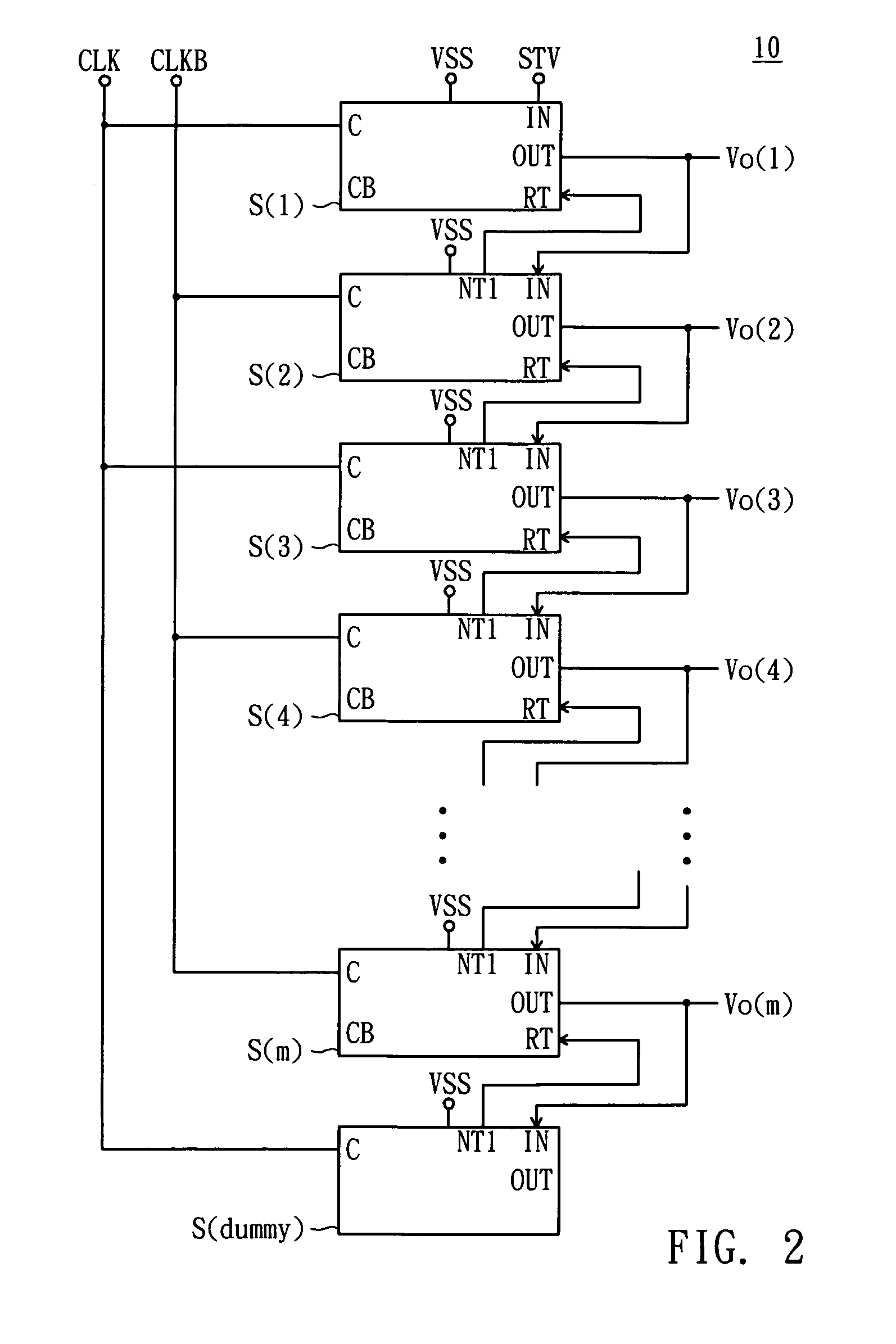
[0045]Referring to FIG. 2, a block diagram of a shift register according to a first embodiment of the invention is shown. A shift register 10 includes m shift register units S(1)-S(m) coupled in series to each other and having the same structure for instance. In the embodiment, each of the shift register units S(1)-S(m) includes an input terminal IN, an output terminal OUT, a control terminal RT, a node NT1, and a timing terminal C. The input terminal IN of the shift register unit S(1) receives a start signal STV and the input terminals IN of the shift register units S(2)-S(m) sequentially receive the scan signals Vo(1)-Vo(m−1) outputted by the output terminal of the previous stage of shift register units S(1)-S(m−1), respectively.

[0046]In the shift register units S(1)-S(m), the timing signals received by any two adjacent timing terminals C have staggered enabling time In the embodiment, the timing terminal C of the odd-stage ones in the shift register units S(1)-S(m) are exemplifie...

embodiment two

[0064]Referring to FIG. 6, a block diagram of a shift register according to a second embodiment of the invention is shown. The difference between the shift register 20 of the embodiment and the shift register 10 of the first embodiment is that each of the shift register units S′(1)-S′(m) further includes a time terminal CB for receiving an inverse clock signal compared to the clock signal received by the corresponding time terminal C.

[0065]In the shift register units S′(1)-S′(m), the timing signals received by any two adjacent timing terminals C have staggered enabling time, the timing signals received by any two adjacent timing terminals CB have staggered enabling time. The timing signals received respectively by the timing terminal CB of the n-th stage of shift register unit S′(n) and the timing terminal C of the (n+1)-th stage of shift register unit S′(n+1) have also staggered enabling time, wherein n is a natural number. In the following description, the n-th stage of shift regi...

example two

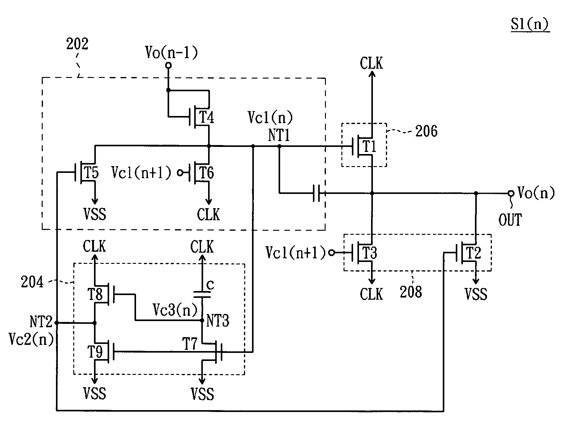
[0068]Referring to FIG. 8, a detailed circuit diagram of the shift register unit in FIG. 6 according to a second example of the second embodiment is shown. The difference between the shift register unit S2′(n) of the example and the shift register unit S1(n) is that the level lowering unit 208 of the example further includes a transistor T10, and the transistor T10 has a gate for receiving the timing signal CLKB, a drain coupled to the output terminal OUT and a source for receiving the voltage VSS. In the time periods TP1 and TP3, the transistor T10 is turned on such that the scan signal Vo(n) is equal to the voltage VSS. Therefore, the level lowering unit 208 of the example can lower down the level of the scan signal Vo(n) via the transistor T10 in the periods TP1 and TP3 to ensure that the scan signal Vo(n) maintains at the low level in the periods TP1 and TP2 and prevent the scan signal Vo(n) from increasing to a high level due to influence of circuit noise. Consequently, in addi...


PUM


Abstract

A shift register includes several stages of shift register units. Each shift register unit includes a first level lifting unit, first level lowering unit, first driving unit and level controller. The first level lifting unit and first level lowering unit control the scan signal to be equal to a first timing signal and first voltage, respectively. The level controller includes an input unit, a charge storage unit, a second level lifting unit and a second level lowering unit. The input unit controls the third control signal to be equal to the first voltage at a node. The charge storage unit stores a voltage of the timing signal at the node. The second level lifting unit and second level lowering unit respectively control the second control signal to be equal to the third control signal and the first voltage to turn on and turn off the first level lowering unit.

Description

[0001]This application claims the benefit of Taiwan application Serial No. 096112779, filed Apr. 11, 2007, the subject matter of which is incorporated herein by reference.BACKGROUND OF THE INVENTION[0002]1. Field of the Invention[0003]The invention relates in general to a shift register, and more particularly to a shift register, which has a level controller performing a level control operation by using charging storage ability of capacitors.[0004]2. Description of the Related Art[0005]Along with increasing technology development, nowadays, the liquid crystal display (LCD) has been widely applied to electronic display products, such as TV, computer monitors, notebook computers, mobile phones or personal digital assistants. The LCD includes a data driver, a scan driver and a liquid crystal display panel. The display panel has a pixel matrix. The scan driver is for sequentially enabling the corresponding pixel rows in the pixel matrix for transmitting pixel data outputted by the data ...

Claims


Application Information

Patent Timeline
Patent Type & Authority Patents(United States)
IPC IPC(8): G11C19/00
CPCG11C19/28G09G3/3677G09G2310/0286G09G2310/0267
Inventor CHAN, CHIEN-TINGWANG, WEN-CHUN
Owner WINTEK CORP
Why Eureka
Try Eureka