Removable surface covering

a surface covering and a technology of abrasive material, applied in the direction of stairs, building components, stairway-like structures, etc., can solve the problems of affecting the appearance of the floor, so as to improve the thermal and sound insulation qualities, improve the adherence, and improve the effect of sanitary conditions

Inactive Publication Date: 2010-04-20
AZULINDUS Y MARTI
View PDF40 Cites 52 Cited by
  • Summary
  • Abstract
  • Description
  • Claims
  • Application Information

AI Technical Summary

Benefits of technology

[0012]When the plates are ceramic parts, they are fixed to the lower supports leaving some separation grooves therebetween so that the water can, via the grooves, reach the lower chamber corresponding to the supports, thus achieving proper run-off or flow of liquid to drain.
[0047]Thus a covering with high resistance to impact, along with a good grip in the join between the different component parts of the covering is obtained.

Problems solved by technology

These coverings can present problems of hygiene, and at the same time they leave a great deal to be desired at the aesthetic level.
These coverings present certain problems, for example, difficulties when it comes to exchanging ceramic parts due to breakage or for any other reason.

Method used


Image

  • Removable surface covering
  • Removable surface covering
  • Removable surface covering

Examples


first embodiment

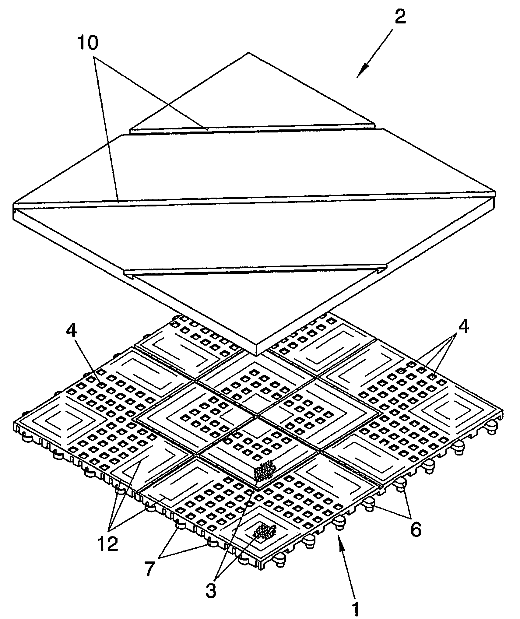
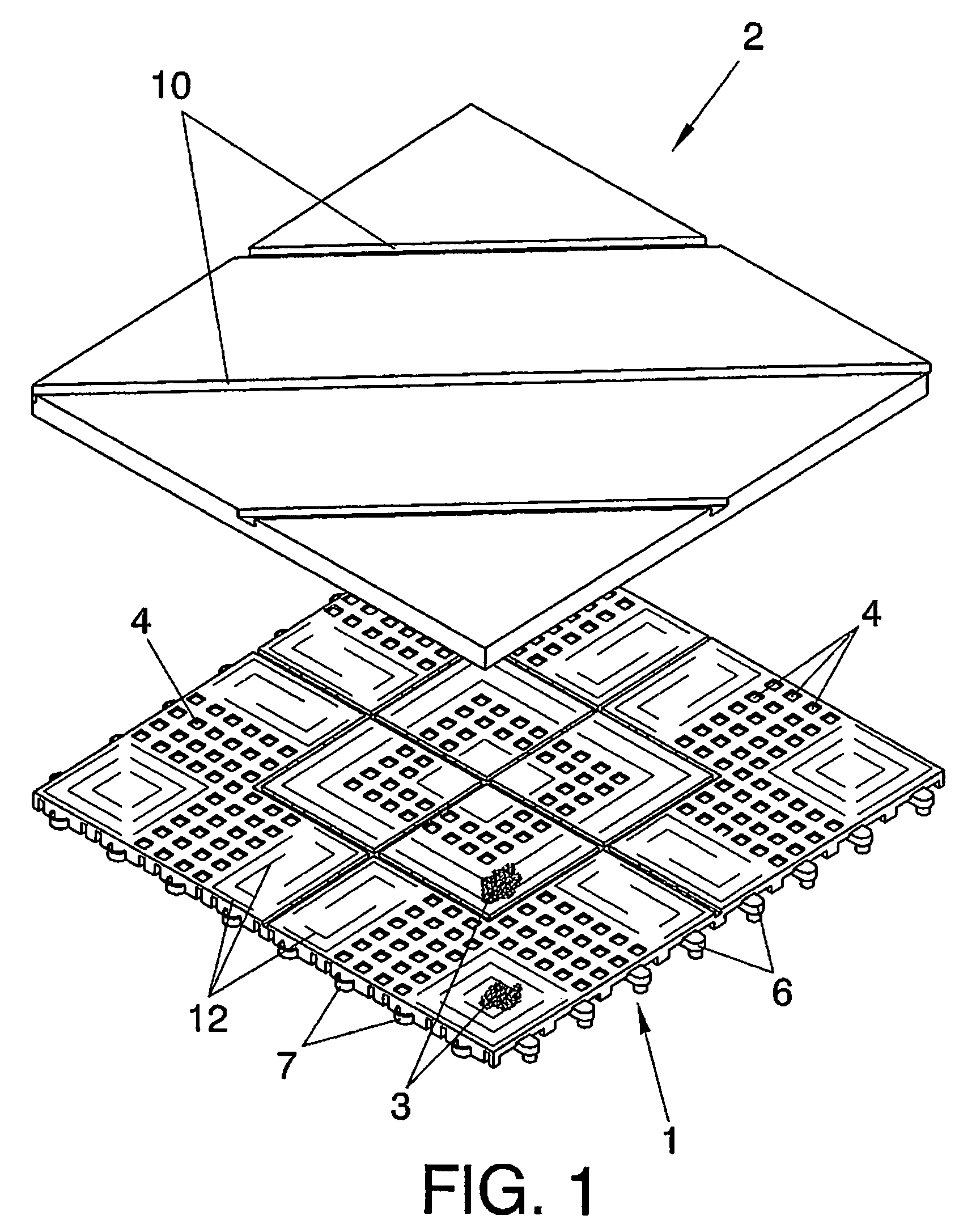
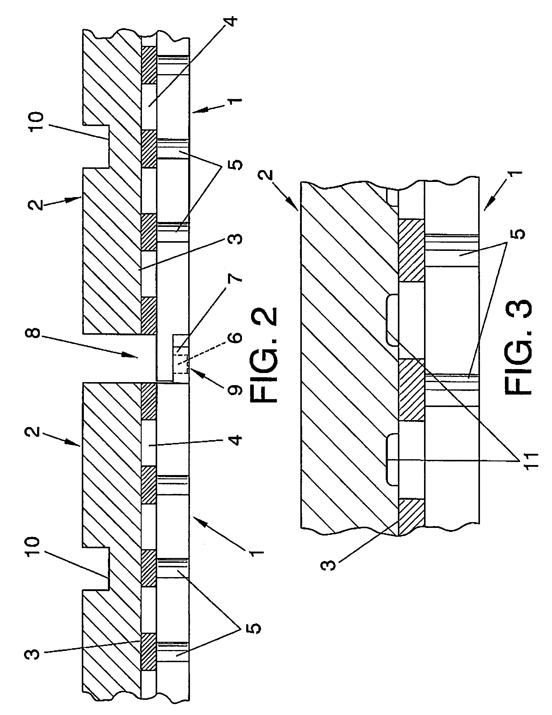
[0060]In a first embodiment, the lower supports 1 include a set of passage windows 4 and also the short support legs 5 on the ground, thereby creating a run-off chamber for rainwater, swimming pool water, etc. The supports 1 also include some grooves 12.

[0061]The lower parts 1 in turn possess complementary anchoring elements 6 and 7 for associating the different lower parts 1 together.

[0062]Moreover, the edges of the upper parts 2 coincide with the edges of the lower supports 1, such that between the upper parts 2 some separation channels 8 are created which coincide with other separation channels 9 existing between the lower parts, these latter channels 9 being where the anchoring elements 6 and 7 between the different lower parts 1 are to be found.

[0063]Thus, the water, which falls on the ceramic parts 2, will reach as far as the run-off chamber precisely via the peripheral channels demarcating and separating the different parts.

[0064]In addition, the ceramic parts 2 can include s...

second embodiment

[0067]In a second embodiment, the adhesive material 3 is located in correspondence with slots 13 of the ceramic parts 2′ and in correspondence with facing hollows of the lower parts 1′.

[0068]As shown in FIG. 5, the hollows include passage openings 14, such that, when the two parts are pressed together, in order to proceed to their joining, the adhesive material, still soft, will adopt a structure in the form of a mushroom 15 by way of a rivet, such that when the adhesive dries, a chemical and mechanical connection will be obtained via the different points where the adhesive has been applied.

[0069]As shown in FIG. 6, the hollows consist of some conical shaped openings 16, such that when the adhesive dries a solid fastening with a rivet structure 17 is obtained.

[0070]The lower supports 1′ include the set of passage windows 4, along with the short support legs 5′ on the ground, thereby creating a run-off chamber for rainwater, swimming pool water, etc., as occurred in the first embodim...


PUM

PropertyMeasurementUnit
areaaaaaaaaaaa
swellingaaaaaaaaaa
thicknessaaaaaaaaaa

Abstract

A removable surface covering comprises a combination of lower supports with plastic support legs and upper ceramic parts which are joined to the supports by contact faces and with the aid of an adhesive material, such as to form covering modules which are interconnected using tongue-and-groove anchoring elements. The plastic supports and the ceramic parts are joined using a thick layer of adhesive which covers almost all of the contact surfaces thereof. In addition, the ceramic parts are equipped with channels and a peripheral notch which house respectively ribs and a frame belonging to the plastic support. The thickness of the adhesive extends over at least part of the thickness of the ribs and the frame of the plastic support. In another embodiment of the invention, the parts are joined at strategic points with a chemical-mechanical connection.

Description

FIELD OF THE INVENTION[0001]The present invention relates to a removable surface covering applicable essentially to floors, terraces, etc., which has the feature of being easily removable and of permitting proper run-off of water and liquids that might fall onto its surface.BACKGROUND OF THE INVENTION[0002]There currently exist different coverings for floors, among which are those which are applied to outdoor surfaces in order to facilitate the run-off of rainwater and also in areas around swimming pools.[0003]In some cases, the coverings include plastic parts with a hollow structure with a certain thickness which define a lower run-off chamber (S1017449).[0004]These coverings can present problems of hygiene, and at the same time they leave a great deal to be desired at the aesthetic level.[0005]In another case, the coverings comprise bodies manufactured from porous materials, which, although capable of draining off a certain flow of water, a certain point is reached at which satura...

Claims


Application Information

Patent Timeline
Patent Type & Authority Patents(United States)
IPC IPC(8): E04F15/00E04F13/08E04F15/22E04F17/00
CPCE04F15/02183E04F15/087Y10T428/24174E04F15/02194
Inventor SANSANO MARTI, VICENTE
Owner AZULINDUS Y MARTI
Why Eureka
Try Eureka