Engine intake air compressor and method

a technology of intake air compressor and compressor, which is applied in the direction of wind motor with parallel air flow, wind motor with perpendicular air flow, liquid fuel engine components, etc., can solve the problems of loss of pressure in the intake passage connected to the inlet of the compressor, and the inability to draw fluid. an adequate amount of fluid

Active Publication Date: 2010-04-20
INT ENGINE INTPROP CO LLC
View PDF16 Cites 39 Cited by
  • Summary
  • Abstract
  • Description
  • Claims
  • Application Information

AI Technical Summary

Problems solved by technology

One main disadvantage of the known engine configurations is their ability to draw an adequate amount of fluid into the compressor.
Another disadvantage is a loss of pressure in an intake passage connected to an inlet of a compressor resulting from the connection of the other flow circuits.

Method used


Image

  • Engine intake air compressor and method
  • Engine intake air compressor and method
  • Engine intake air compressor and method

Examples


Embodiment Construction

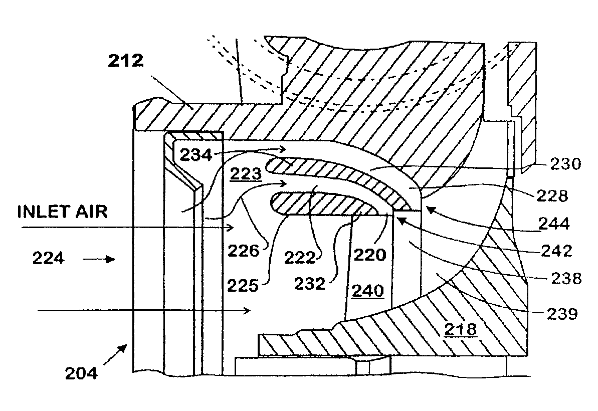
[0022]The following describes an apparatus for and method of providing additional inputs for a compressor for use with an internal combustion engine. Although the invention is applicable to a mechanically-driven supercharger, this description is in the context of an exhaust-gas-driven turbocharger. An improved compressor 100 in accordance with the invention is shown in FIG. 1. The compressor 100 has a housing 112 enclosing a compressor wheel 118. The housing 112 in the area of the wheel 118 has features that enhance performance of the compressor 104. A secondary inducer slot 120 fluidly connects an inlet chamber 122 with an inducer bore 125. A ring slot 126 that fluidly connects the chamber 122 with the air intake 124 is formed between an inlet wall 128 and an inlet ring 130. The recirculation chamber 122 is separated from the main air intake 124 by the inlet wall 128. The inlet chamber 122 is the annular volume between the housing 112, the inlet wall 128 and the inlet ring 130.

[002...


PUM


Abstract

A compressor assembly (304) includes a compressor housing (312) having a main air inlet (324) and an annular wall (328) defining an inducer bore (325). A secondary inlet passage (322) is disposed around the inducer bore (325). The secondary inlet passage (322) has an inlet slot (320) operatively intersecting the inducer bore (325) to permit the entry of a fluid thereinto through an inlet port (327). The inlet slot (320) advantageously defines an augmented inducer diameter region (331). Preferably the secondary inlet passage (322) may be selectively partially or completely isolated from the main air inlet (324). A compressor wheel (318) is located in the compressor housing (312) and has a stepped portion (330) formed by at least one plurality of vanes (238) operatively associated with the augmented inducer diameter region (331) adjacent to the inlet slot (320) of the housing (312) to receive fluid therefrom.

Description

FIELD OF THE INVENTION[0001]This invention relates to intake air compressors, such as turbochargers or superchargers, for internal combustion engines.BACKGROUND OF THE INVENTION[0002]Engines having compressors for intake air, such as turbochargers or superchargers are well known. Engine systems employing fluid input paths upstream of a compressor inlet are also known.[0003]There have been many attempts to optimize the air management function of an engine that includes more than air intake and exhaust paths. An engine may include associated flow circuits, for example, exhaust gas recirculation, crankcase breather, electronics cooling, or other flow circuits that may be connected between an engine location and an inlet to a compressor or supercharger.[0004]One main disadvantage of the known engine configurations is their ability to draw an adequate amount of fluid into the compressor. Another disadvantage is a loss of pressure in an intake passage connected to an inlet of a compressor...

Claims


Application Information

Patent Timeline
Patent Type & Authority Patents(United States)
IPC IPC(8): F04D29/38
CPCF02B37/22F02M25/0709F04D29/685F04D29/4213F02B33/40F02M23/00F02M25/06F02M25/0798F05B2220/40Y02T10/121Y02T10/144F02M25/0724F02M26/06F02M26/21F02M26/51Y02T10/12
Inventor WOOD, TERRY G.SOUPOS, ELIAS P.
Owner INT ENGINE INTPROP CO LLC
Why Eureka
Try Eureka