Mold assembly for glass articles

a technology of molds and glass articles, applied in glass rolling apparatus, glass tempering apparatus, manufacturing tools, etc., can solve the problems of limiting the rate at which heat can be removed, reducing the efficiency of forming machines, and removing heat at a large rate, so as to improve the indirect cooling rate of molten glass articles, reduce the manufacturing cost of molds, and increase the rate of latent hea

Inactive Publication Date: 2010-04-20
OWENS-BROCKWAY GLASS CONTAINER INC
View PDF33 Cites 14 Cited by
  • Summary
  • Abstract
  • Description
  • Claims
  • Application Information

AI Technical Summary

Benefits of technology

[0005]According to the present invention there is provided a mold assembly for a glass forming machine of the I.S. type. The mold assembly includes an annular mold, which is made up of a mating pair of mold sections, whose internal surface, when the mold sections are joined end to end, defines the external shape of a glass article to be formed in an internal cavity of such annular mold, either the final shape of a glass article in the case of a blow mold or the shape of a preform of such article in a blank mold. The exterior of each of the mold sections is provided with a circumferential plurality of radially projecting, axially extending spaced apart ribs to extend the surface of the mold sections to thereby increase the rate at which latent heat can be removed from the molten glass article within the mold.
[0006]The mold assembly also includes a split mold holder for holding the mold sections of a mold, as heretofore described. The mold holder, which is suitable for use with a variety of molds, surrounds the mold and directs air or other cooling fluid radially inwardly against the ribs on the exterior of the mold sections from radially open, axially extending flow passages. A split, perforated screen is applied to the interior of each of the sections of the

Problems solved by technology

Thus, much heat must be removed from the container being formed, both during the blank molding step and the blow molding step, and unless the heat is removed at a rapid rate, the productivity of the forming machine is unduly limited.
The problem of heat removal from the molds of an I.S. forming machine at a suitable rate is especially important at the blank mold station because the surface area of the parison is quite small due to the small diameter of the parison, which limi

Method used


Image

  • Mold assembly for glass articles
  • Mold assembly for glass articles
  • Mold assembly for glass articles

Examples


Embodiment Construction

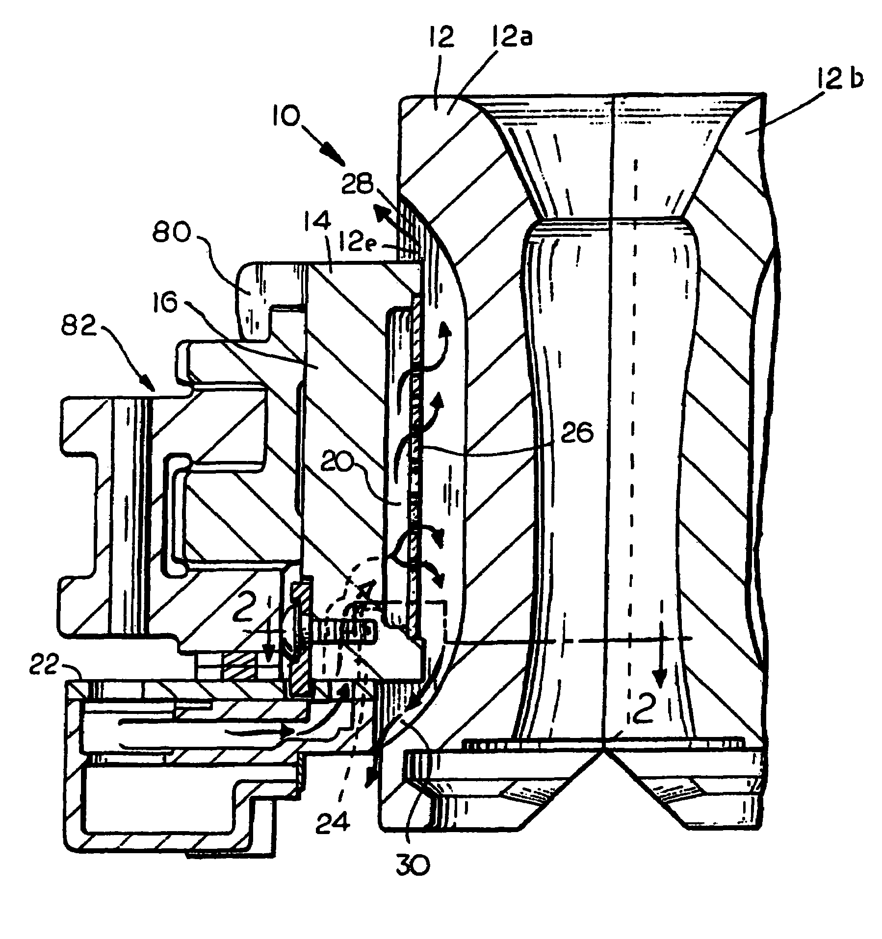
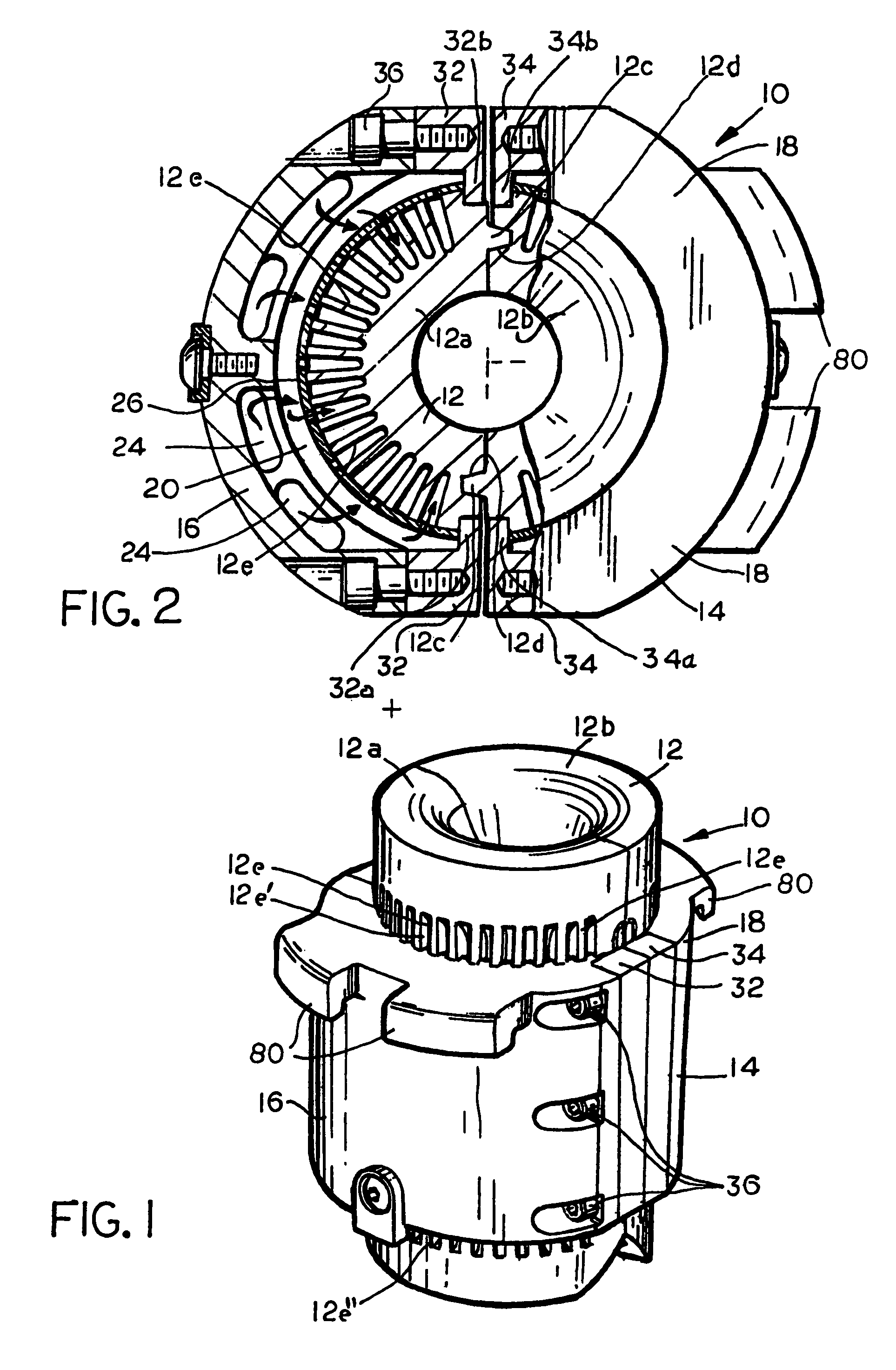
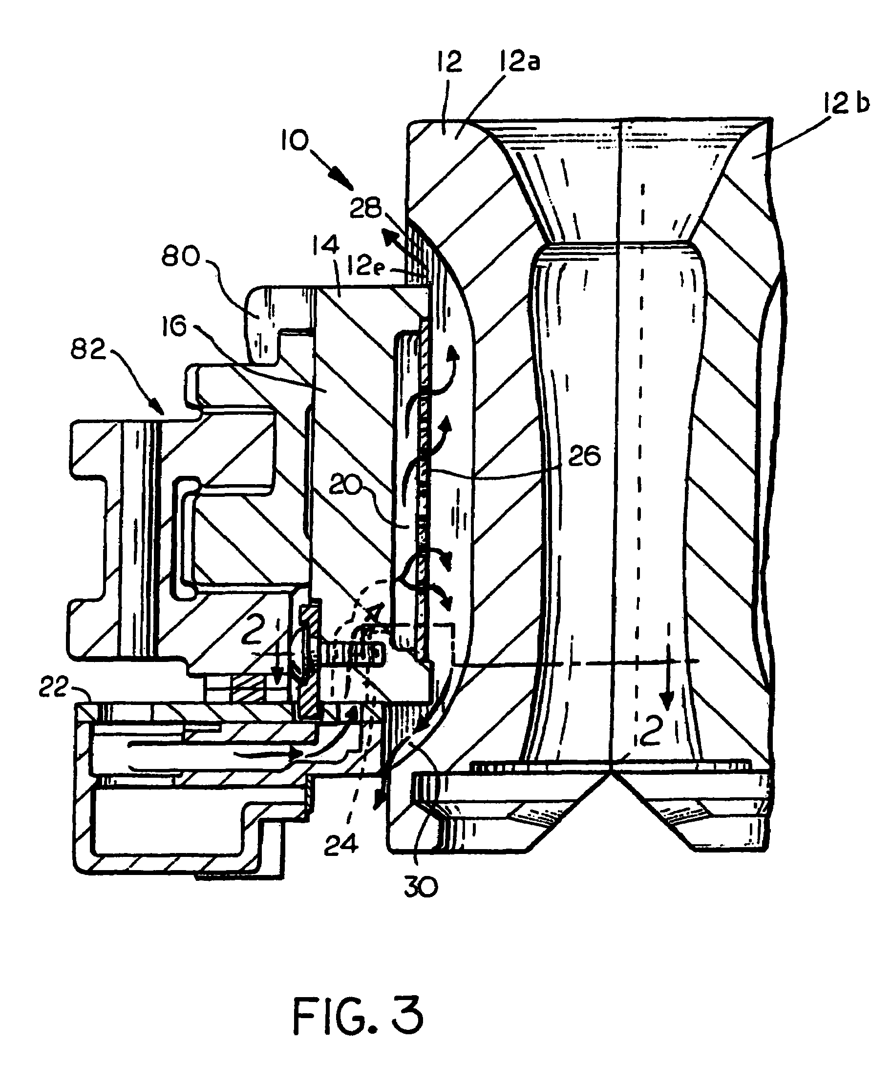
[0019]A mold assembly according to the preferred embodiment of the present invention is identified generally by reference numeral 10 in FIG. 1, and is made up of an annular mold 12, which is illustrated as being suitable for use in forming a parison of a glass container. The mold assembly 10 also includes an annular mold holder 14, which encloses a substantial portion of the axial length of the mold 12 and is a part of an I.S. glass container forming machine or at least is a part that does not need to be replaced when the mold 12 is replaced.

[0020]The annular mold 12 is made up of generally semi-cylindrical mold elements 12a, 12b, which, when joined end to end during a molding operation, substantially enclose a glass article being molded in a cavity therein. The mold elements 12a, 12b are separable from one another at the conclusion of a molding step, to permit a molded article to be removed therefrom, as is known in the art. In that regard, each of the mold elements 12a, 12b is pro...


PUM

PropertyMeasurementUnit
Lengthaaaaaaaaaa
Flow rateaaaaaaaaaa
Shapeaaaaaaaaaa

Abstract

A mold assembly (10; 40) for molding a hollow glass article comprising a mold (12) that is made up of a separable pair of mold elements (12a, 12b; 42) and a mold holder (14; 44) that surrounds a portion of the mold of substantial axial length. The mold is separable from the mold holder, and the exterior of each mold segment is provided with a plurality of cooling fins (12e; 42e). The mold holder is made up of a separable pair of mold holder sections (16, 18; 46), and each mold holder section has a fluid flow passage (20; 50) extending therethrough. The fluid flow passage is radially open to permit fluid flowing therethrough to flow inwardly against the fins of an adjacent mold element. Each mold holder section has a perforated screen (26; 56) affixed thereto to vary the distribution of the flow of fluid from the mold holder section against the fins of the adjacent mold element.

Description

FIELD OF THE INVENTION[0001]This invention relates to a mold assembly for use in forming hollow glass articles on a forming machine of the individual section (“I.S.”) type. More particularly this invention relates to a mold assembly of the foregoing character that provides positive, indirect cooling of the article being molded in the mold assembly.BACKGROUND OF THE INVENTION[0002]Hollow glass articles, such as bottles and jars, when molded by a forming machine of the I.S. type, are molded in two steps. In the first step, a preform of the finished container, which is usually called a blank or a parison, is molded by an annular mold made up of a pair of mating blank mold sections. Upon the completion of the blank molding step, the blank mold sections separate and the blank or parison is transferred to another mold station, often called the blow mold station, where it is blown into its final shape by another annular mold that is made up of another mating pair of mold sections. At the c...

Claims


Application Information

Patent Timeline
IPC IPC(8): C03B9/38C03B9/197C03B9/353C03B11/06C03B11/12
CPCC03B9/3875C03B9/353
Inventor HAYES, DAN M.HAUSER, RUSSELL M.OLSON, DUDLEY T.NUZUM, ROBERT E.
Owner OWENS-BROCKWAY GLASS CONTAINER INC
Why Eureka
Try Eureka