Screw attachment, fastening assembly having screw attachment, and process of releasing fastening assembly

Inactive Publication Date: 2010-04-20
SHARP KK +3
View PDF38 Cites 8 Cited by
  • Summary
  • Abstract
  • Description
  • Claims
  • Application Information

AI Technical Summary

Benefits of technology

[0020]In view of the aforementioned situation, an object of the invention is to provide a screw attachment, a fastening assembly having the screw attachment, and a process of releasing the fastening assembly, which are suitable for securing a fastening member to an opposing object with reliability and efficient work and also for removing or separating the fastening member from the opposing object with ease.

Problems solved by technology

However, it takes time to remove securing screws of the electric appliances.
Thus, a recycling process with sufficient work efficiency has not been established yet.
Thus, the washer 62 is difficult in minimization not to be applied to a small screw.
Therefore, a heating process after fastening of the screws to increase the fastening force like the first prior art will be disadvantageous in work efficiency for the assembling step.
Such a heating process step will be difficult for obtaining a constant fastening force, decreasing productivity of the assembling step.
The screw 70 may be disadvantageously loosened due to vibration of the electric appliance.
Furthermore, the screw 70 requires a thread formed thereon with a rotating dice, increasing an assembling cost of the electric appliance.
On the contrary, the increased fastening force is disadvantageous when the bolt is removed during disassembling of the electric appliance.
The larger contact pressure may undesirably prevent a washer form releasing from the bolt when the washer is heated for disassembling of an electric appliance.
Meanwhile, such a connection piece is undesirable for easily disassembling an electric appliance, because the screw having the connection piece is not easily removed.

Method used


Image

  • Screw attachment, fastening assembly having screw attachment, and process of releasing fastening assembly
  • Screw attachment, fastening assembly having screw attachment, and process of releasing fastening assembly
  • Screw attachment, fastening assembly having screw attachment, and process of releasing fastening assembly

Examples


Embodiment Construction

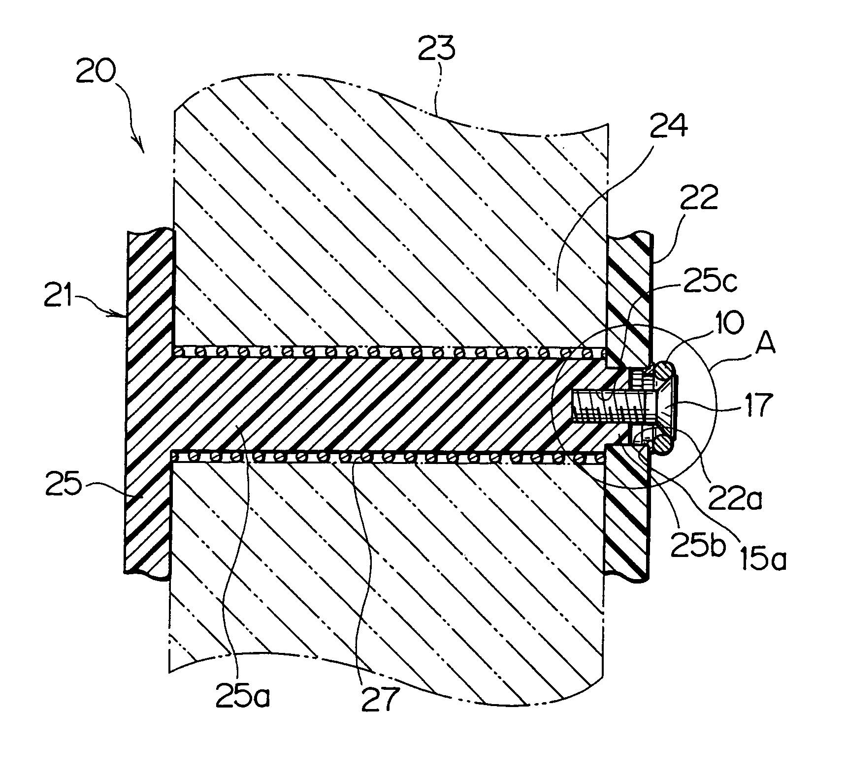
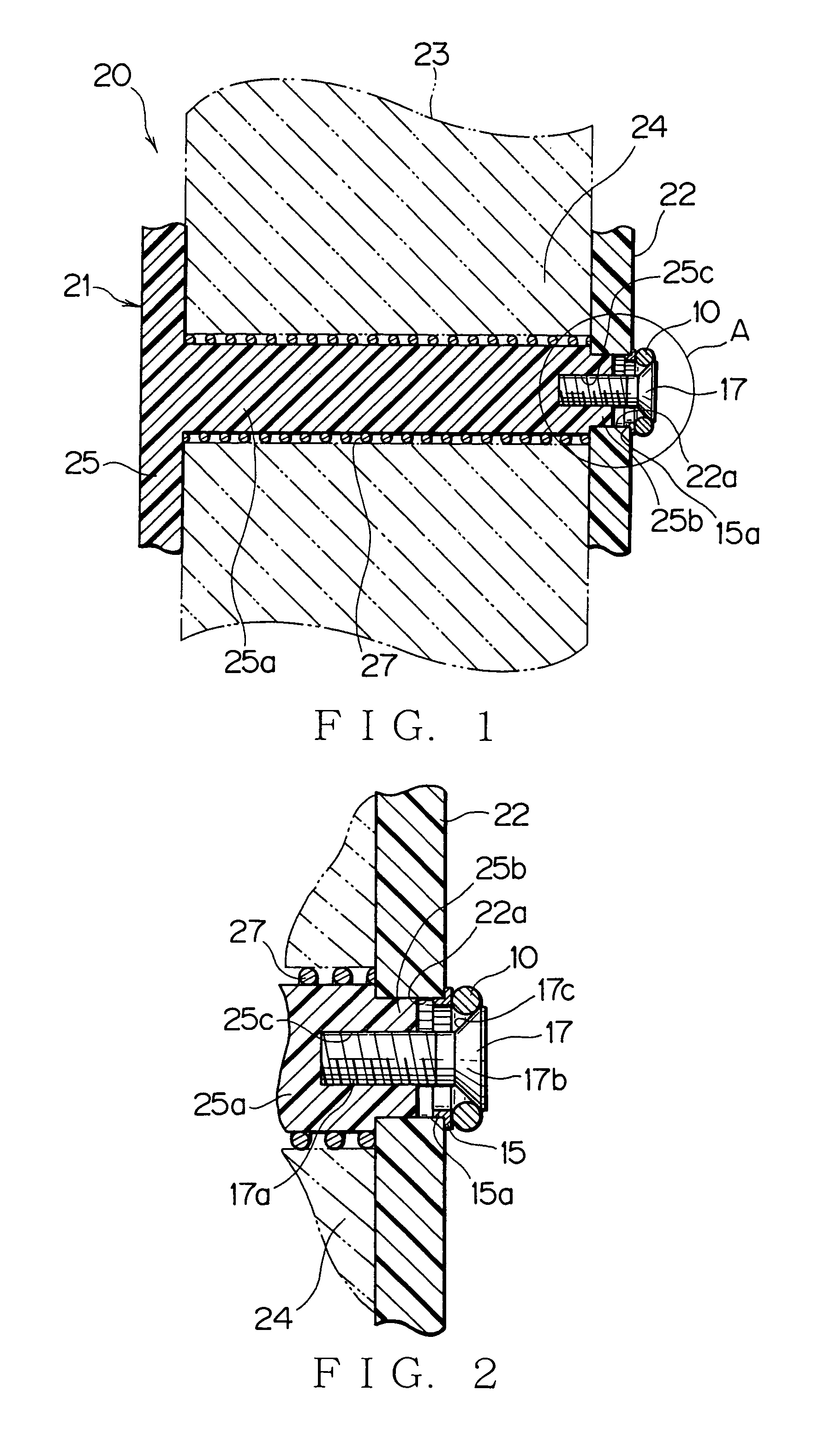
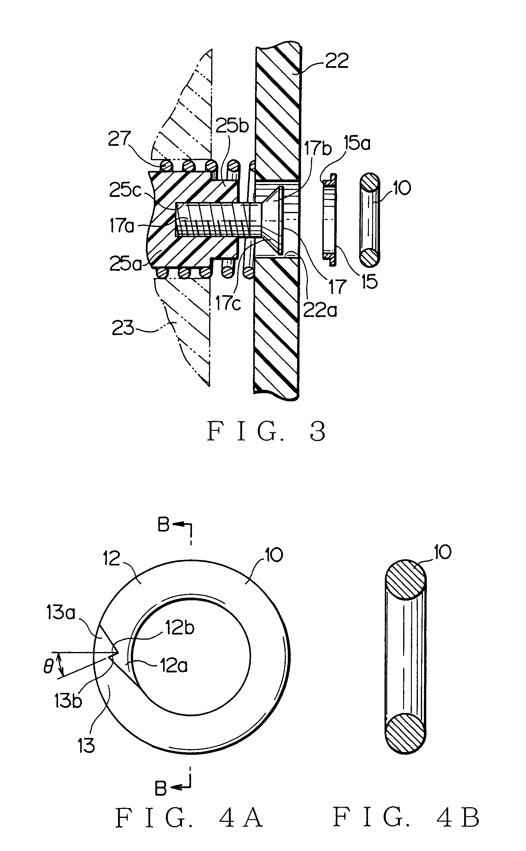
[0076]Embodiments of the present invention will be discussed hereinafter. FIGS. 1 to 5 show a first embodiment of a screw attachment, a fastening assembly having the screw attachment, and process of releasing the fastening assembly according to the present invention.

[0077]FIG. 1 shows partially a liquid-crystal television 20 to discuss an example of a fastening assembly. The fastening assembly employs a spacer (screw attachment) 10 made of a shape memory alloy for an easy disassembling process. The liquid-crystal television 20 has a plastic chassis 21 to receive a box, a liquid crystal panel body 23, lamps (not shown), sheets (not shown), etc. The chassis 21 consists of a panel case 25 and a panel cover (securing object) 22 covering an opening of the liquid crystal panel body 23. The liquid crystal panel body 23 has a pair of fore and rear glass plates, a liquid crystal sheet, a deflection plate, a reflection plate, an electronic circuit unit, etc. The liquid crystal panel body 23 i...


PUM

PropertyMeasurementUnit
Forceaaaaaaaaaa
Shapeaaaaaaaaaa

Abstract

A screw attachment (10, 10′, 10″) disposed around a fastening piece (17) secured to a main fastening body (25a), the screw attachment sandwiched between a head (17b) of the fastening piece and a securing object (22) so that the screw attachment bears a securing force of the fastening piece to press the securing object. The screw attachment includes a pair of arms (12, 13) made of a shape restoring material. Each arm has a fore end, and the fore ends are joined to each other with an adhesive material that is softened when heated. The arms expands radially such that the screw attachment is released from the head of the fastening piece when heat or force is applied to the arms.

Description

BACKGROUND OF THE INVENTION[0001]1. Field of the Invention[0002]The present invention relates to a screw attachment, a fastening assembly having the screw attachment, and a process of releasing the fastening assembly, which are effectively applied to an instrument or machine which can be recycled such as an air conditioner, a refrigerator, a television, a battery pack, and a convenient charger.[0003]2. Background Art[0004]Recycling of electric appliances such as an air conditioner, a washing machine, and a refrigerator has been positively realized for reuse of natural resources in view of environmental preservation. However, it takes time to remove securing screws of the electric appliances. Thus, a recycling process with sufficient work efficiency has not been established yet.[0005]FIGS. 16 to 18 show examples of fastening pieces and screw attachments which are made of shape memory alloys. A first prior art as disclosed in Japanese Utility Model Laid-open No. H-2-36616 (particularl...

Claims


Application Information

Patent Timeline
IPC IPC(8): F16B37/04F16B21/18F16B43/02C22C9/00C22C19/03F16B5/02F16B43/00
CPCF16B5/02F16B21/18F16B43/004Y10T403/75Y10T29/49821F16B1/00F16B43/00F16B21/00
Inventor SUGIYAMA, KAZUOTASHIMA, TADASHIYOSHIDA, KAZUNARIKAGAMI, YUTAKAARA, HIDEOSHINDOH, YOSHIOTANIGAWA, MASANOBU
Owner SHARP KK
Why Eureka
Try Eureka