Robotically controlled surgical instruments

a robotic and surgical instrument technology, applied in the field of robotic controlled surgical instruments, can solve the problems of quite complex repetition movements, and achieve the effect of minimizing operator fatigue and increasing grasping for

Active Publication Date: 2010-04-20
AURIS HEALTH INC
View PDF279 Cites 1516 Cited by
  • Summary
  • Abstract
  • Description
  • Claims
  • Application Information

AI Technical Summary

Benefits of technology

[0007]The instrument may include a drive mechanism that increases the force applied to an item grasped between the jaws. The drive mechanism and the jaws can be provided with an accommodating mechanism that allows continued movement of the drive mechanism towards a locked position even after the jaws contact a larger item so that the drive mechanism can move to the locked position when grasping items of different sizes.
[0009]In some embodiments, the drive mechanism includes a linkage comprising two links joined by a link pin. One link has a first end connected by a pivot joint to the first jaw and a second end provided with the link pin positioned in a slot of the second jaw, the slot having a curved segment and a relatively straight segment. The two segments together form a slot with a J-shape. The link pin is driven along the straight segment through another link by a driver pin that follows the curved segment. The linkage provides increasing leverage to increase the force applied to the item grasped between the jaws as the link pin moves along the straight segment away from the curved segment. In such embodiments, the accommodating mechanism can be an extended end segment of the slot that extends from the straight segment. The link pin resides in the end segment when the jaws grasp an item. The extent to which the link pin resides in the segment depends upon the size of the item being grasped.
[0012]In some embodiments, a robotically controlled medical instrument coupled to a robotic controller includes an instrument shaft having proximal and distal ends, and a tool supported from the distal end of the instrument shaft and useable in performing a medical procedure on a subject. The tool is constructed and arranged so to be capable of receiving different size items and includes a pair of work members, a drive mechanism which increases the force applied to an item grasped between the work members, and an accommodating mechanism interacting with the drive mechanism and work members and that allows the work members to be closed beyond a maximum grasping position so that the work members can grasp items of various size.
[0013]Some embodiments may have one or more of the following advantages. The medical instrument is able to grasp items of different sizes. Thus, a single instrument may be used to grasp items including, but not limited to, needles, sutures, tissue, and blood vessels. The J-slot provides mechanism to lock the jaws onto the grasped item. Hence, the grasped item cannot inadvertently fall out of the instrument. Moreover, the leverage action of the drive mechanism allows the surgeon to apply an increasing grasping force to the item, and therefore minimizes operator fatigue.

Problems solved by technology

Because these replicated movements can be quite complex, the surgical instrument is controlled to move with multiple degrees-of-freedom.

Method used


Image

  • Robotically controlled surgical instruments
  • Robotically controlled surgical instruments
  • Robotically controlled surgical instruments

Examples


Embodiment Construction

[0088]A description of preferred embodiments of the invention follows.

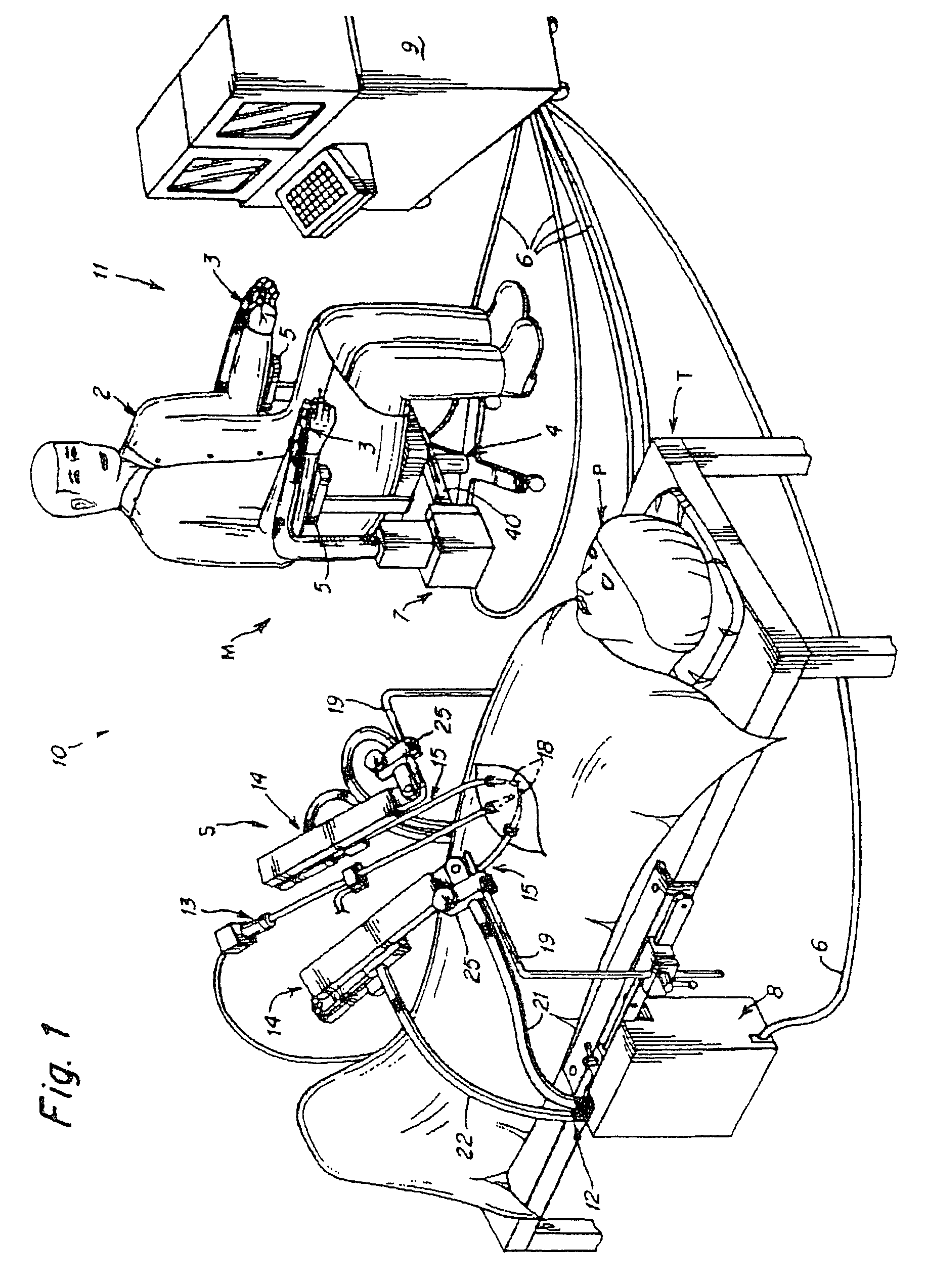
[0089]The surgical robotic system of the present invention, as illustrated in the accompanying drawings, although preferably used to perform minimally invasive surgery, can also be used to perform other procedures as well, such as open or endoscopic surgical procedures. FIG. 1 illustrates a surgical instrument system 10 that includes a master station M at which a surgeon 2 manipulates an input device, and a slave station S including a surgical instrument illustrated generally at 14. In FIG. 1 the input device is illustrated at 3 being manipulated by the hand or hands of the surgeon. The surgeon is illustrated as seated in a comfortable chair 4, and the forearms of the surgeon are typically resting upon armrests 5.

[0090]FIG. 1 illustrates a master assembly 7 associated with the master station M and a slave assembly 8, also referred to as a drive unit, associated with the slave station S. Assemblies 7 and 8 are inte...


PUM


Abstract

A robotically controlled surgical instrument includes a first jaw and a second jaw used to grasp an item, and a drive mechanism that increases the force applied to the item grasped. The drive mechanism and the jaws can be provided with an accommodating mechanism that allows continued movement of the drive mechanism towards a locked position even after the jaws contact a larger item so that the drive mechanism can move to the locked position when grasping items of different sizes.

Description

RELATED APPLICATIONS[0001]This application claims the benefit of U.S. Provisional Application No. 60 / 427,525 filed Nov. 18, 2002 and U.S. Provisional Application No. 60 / 493,425 filed on Aug. 7, 2003 and is a continuation-in-part of U.S. application Ser. No. 10 / 014,143 now abandoned; Ser. No. 10 / 008,964 now abandoned; Ser. No. 10 / 013,046 now abandoned; Ser. No. 10 / 011,450 now abandoned; Ser. No. 10 / 008,457 now U.S. Pat. No. 6,949,106; Ser. No. 10 / 008,871 now U.S. Pat. No. 6,843,793; and Ser. No. 10 / 012,845, all filed on Nov. 16, 2001, each of which claims the benefit of U.S. provisional Application No. 60 / 279,087 filed Mar. 27, 2001, and each of which claims the benefit of priority from U.S. application Ser. No. 09 / 827,643 filed Apr. 6, 2001 which claims priority to, U.S. Provisional Application No. 60 / 257,869 filed Dec. 21, 2000 and U.S. Provisional Application No. 60 / 195,264 filed Apr. 7, 2000.[0002]This application is also a continuation-in-part of U.S. application Ser. No. 10 / 023...

Claims


Application Information

Patent Timeline
Patent Type & Authority Patents(United States)
IPC IPC(8): A61B17/00A61B17/04A61B17/28A61B19/00
CPCA61B17/062A61B19/2203A61B2017/2931A61B2017/003A61B2017/00477A61B2017/2902A61B2017/2927A61B2017/2934A61B2017/2936A61B2017/2943A61B2019/2211A61B2019/2223A61B2019/223A61B2019/2234A61B2019/2242A61B17/29A61B34/71A61B2034/301A61B34/30A61B34/37A61B34/35A61B2034/305
Inventor LEE, WOOJINCHAMORRO, III, ANDRESAILINGER, ROBERTMEGLAN, DWIGHT
Owner AURIS HEALTH INC
Why Eureka
Try Eureka