Method of performing anastomosis

a technology of anastomosis and apparatus, applied in the field of apparatus and method for performing anastomosis, can solve the problems of emboli detachment, time-consuming and difficult suturing process, and high surgical skill, and achieve the effect of reducing the risk of emboli disintegration

Inactive Publication Date: 2010-04-20
AESCULAP AG
View PDF213 Cites 1307 Cited by
  • Summary
  • Abstract
  • Description
  • Claims
  • Application Information

AI Technical Summary

Benefits of technology

[0006]In one aspect of the invention, an anastomosis tool includes a tissue effector connected to a handle by a shaft or other structure. The tissue effector may be orientable relative to the handle and / or shaft. For example, the tissue effector may be configured to roll, pitch and / or yaw relative to the shaft. In this way, the tissue effector can be placed in a desired orientation at an anastomosis site, and the handle can be held in a convenient position by the user.
[0013]In another aspect of the invention, at least one graft clip blade optionally is attached to at least one of the arms of the staple holder. The graft clip blade has a serrated edge oriented to engage the corresponding flap of the graft vessel. The serrations on the edge of the graft clip blade assist in holding the corresponding flap securely, particularly as the vein knife incises excess tissue from the flap. Additionally, the graft clip blade may participate in incising excess tissue from the corresponding flap. Further, the serrations on the edge of the graft clip blade, in conjunction with the spikes, may assist in holding the excess tissue incised from each flap.
[0015]In another aspect of the invention, the distal end of one or more of the arms of the staple holder may be notched. After the staples have been deployed, the sled may be positioned such that its distal ends are located at the distal ends of the channels, such that the sled is visible via the notches. In this way, actuation of the sled and thus deployment of the staples can be visually confirmed.
[0017]In another aspect of the invention, the trigger is connected to a rocker that is configured to engage a proximal slider during actuation of the trigger. A first cable or other force transmission structure or mechanism is connected to the proximal slider, as well as to the anvil. The first cable is movable relative to a cable housing, which is fixed at one end to the staple holder and at the other end to the shaft. The anvil is fixed relative to the shaft as well. As the trigger is actuated, the rocker urges the proximal slider proximally, causing the proximal slider to pull the first cable proximally. Because the anvil is fixed relative to the shaft, the proximal motion of the first cable tensions the first cable. Because the cable housing is fixed to the staple holder, the tensioning of the first cable causes the staple holder to move closer to the anvil, thereby moving the tissue effector from the open position to the closed position. By moving the staple holder and keeping the anvil substantially stationary, the tissue effector closes without damaging the target vessel within which the anvil is positioned.

Problems solved by technology

The suturing process is a time consuming and difficult procedure requiring a high level of surgical skill.
This suturing requires a high degree of precision and is quite time consuming.
The use of a side clamp or similar device can cause emboli to detach from the wall of the aorta and enter the bloodstream, which is undesirable.

Method used


Image

  • Method of performing anastomosis
  • Method of performing anastomosis
  • Method of performing anastomosis

Examples


Embodiment Construction

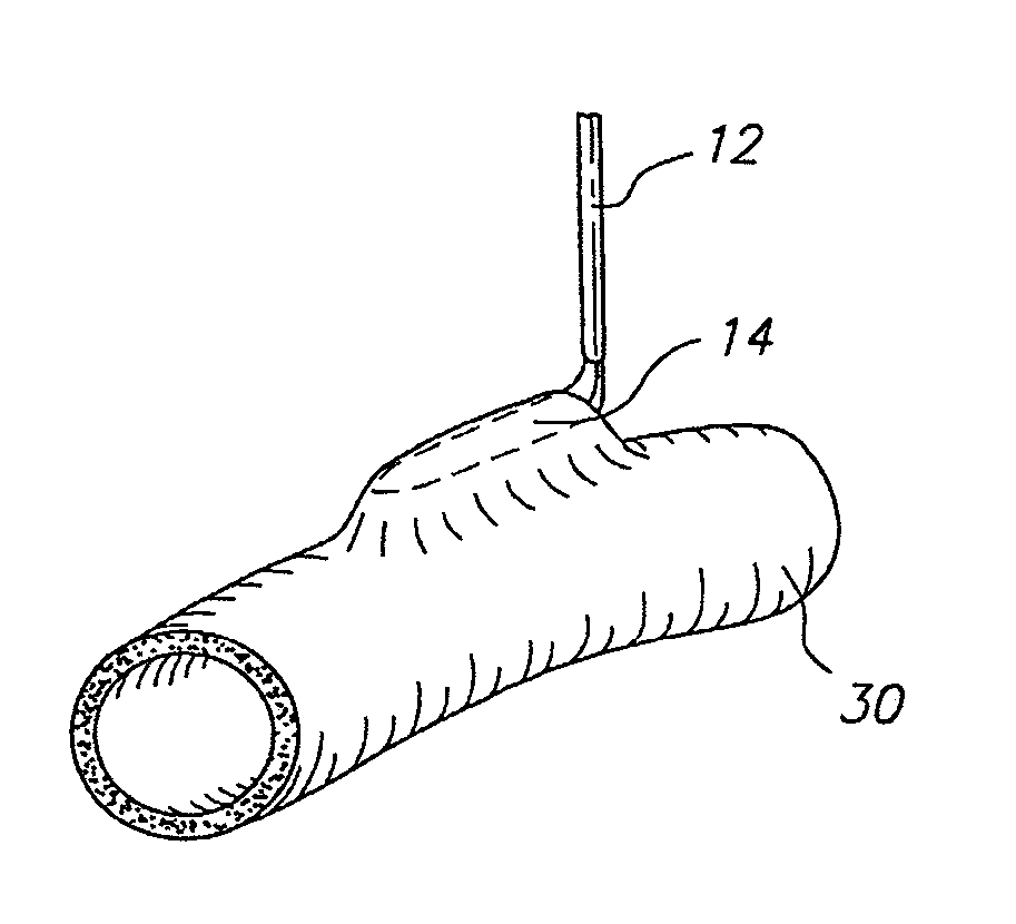
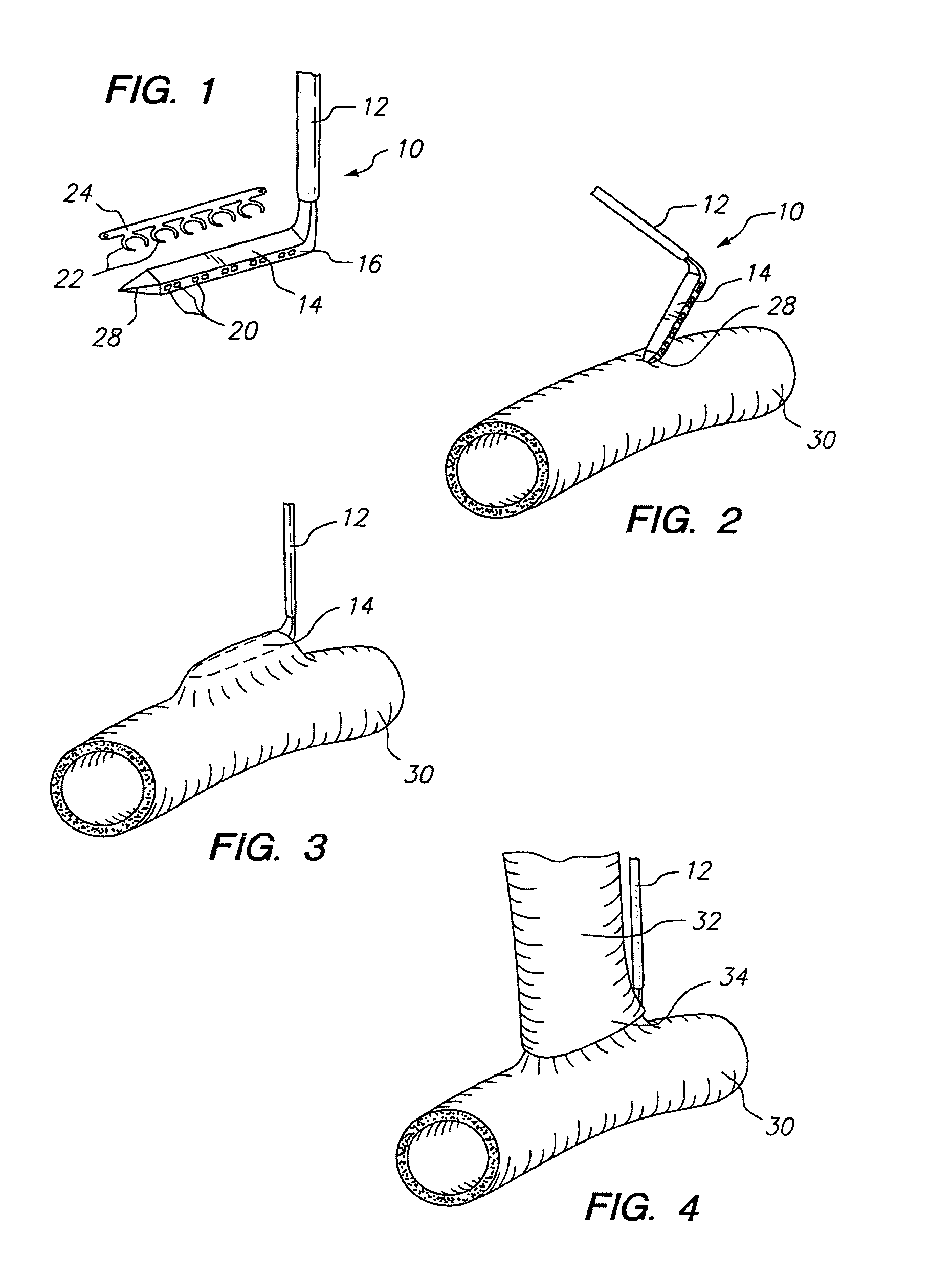
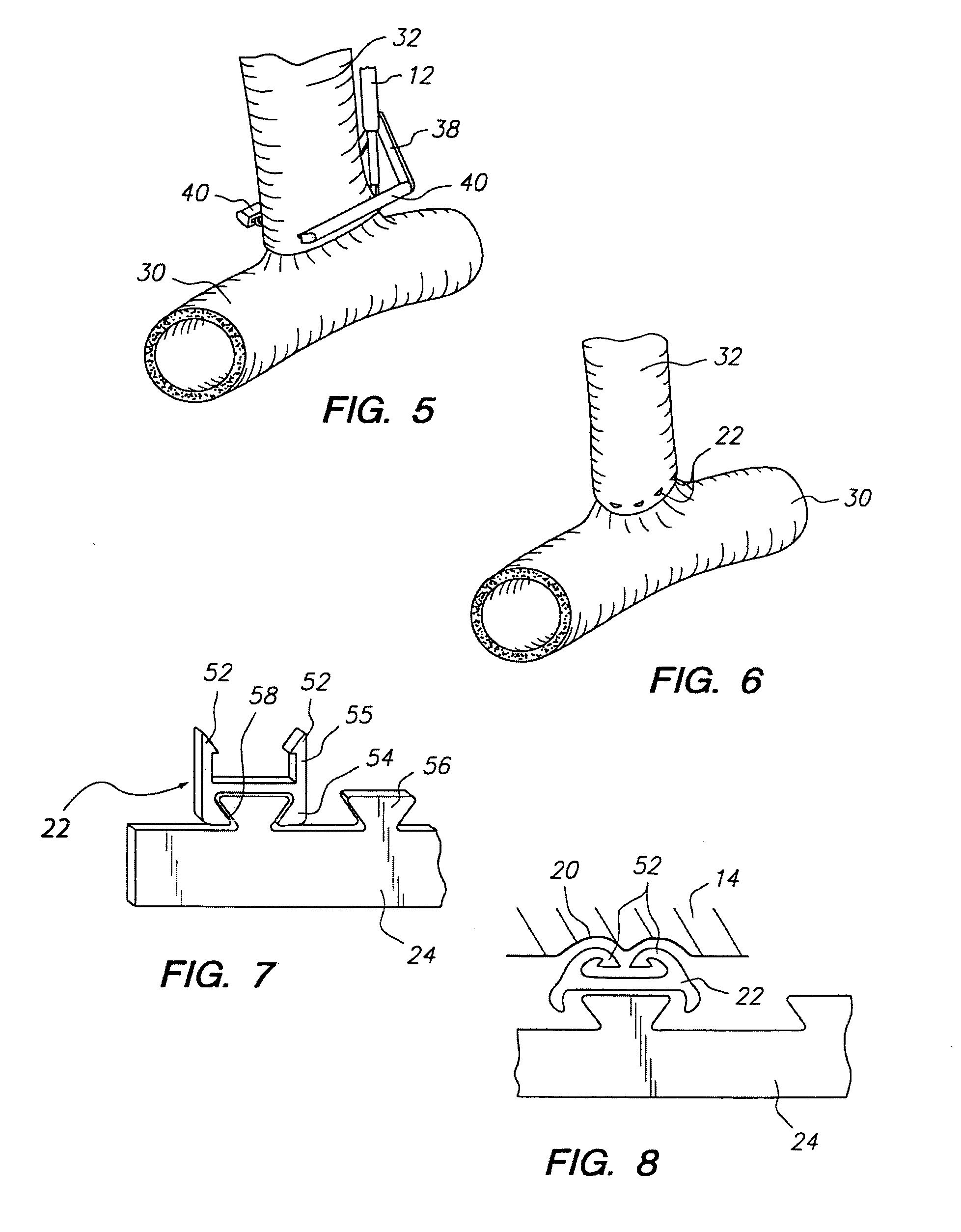
[0101]As shown in FIG. 1, one embodiment of an anvil 10 includes a handle 12 and an anvil arm 14 extending from the handle 12. The anvil arm 14 may be oriented substantially perpendicular to the handle 12, or oriented at a different angle. The anvil arm 14 may be provided with one or more staple bending features 16 on opposite sides of the anvil arm 14. In the anvil 10 shown in FIG. 1, the staple bending features 16 each include a plurality of recesses 20 which receive the ends of staples 22 and cause the staple ends to bend over. At least one of the staple bending features 16 may be configured differently or omitted, if desired. The staples 22 may be connected to a staple holding strip 24. The staples 22 are U-shaped and are arranged in a spaced apart parallel configuration such that the staples 22 all lie in a single plane. Alternately, the staples 22 may be shaped differently, and / or lie in one or more different planes. An exemplary anvil arm 14 has a height and a width of about ...


PUM

PropertyMeasurementUnit
lengthaaaaaaaaaa
lengthaaaaaaaaaa
lengthaaaaaaaaaa

Abstract

A method for anastomosing a first vessel to a second vessel may include connecting an end of the first vessel to the side of the second vessel and creating an opening in the wall of the second vessel from within the lumen of the second vessel, where that opening allows fluid communication between the lumen of the first vessel and the lumen of the second vessel.

Description

[0001]This application is a continuation of U.S. patent application Ser. No. 10 / 392,336, filed Mar. 19, 2003 which in turn is a continuation-in-part of U.S. patent application Ser. No. 10 / 151,441, filed May 20, 2002 now U.S. Pat. No. 7,285,131 which in turn is a continuation-in-part of U.S. patent application Ser. No. 09 / 363,255 filed Jul. 28, 1999, now U.S. Pat. No. 6,391,038. Additionally, this application claims priority to U.S. Provisional Patent Application Ser. No. 60 / 399,880, filed on Jul. 31, 2002.FIELD OF THE INVENTION[0002]The invention relates to an apparatus and method for performing anastomosis.BACKGROUND[0003]Anastomosis is a procedure by which two hollow tissue structures are joined together. More particularly, vascular anastomosis is a procedure by which two blood vessels within a patient are surgically joined together. Vascular anastomosis is performed during treatment of a variety of conditions including coronary artery disease, diseases of the great and peripheral...

Claims


Application Information

Patent Timeline
Patent Type & Authority Patents(United States)
IPC IPC(8): A61B17/08A61B17/00A61B17/04A61B17/072A61B17/11A61B17/115A61B17/122A61B19/00A61F2/06
CPCA61B17/1152A61B17/0469A61B17/072A61B17/122A61B2017/00243A61F2/064A61B2017/07214A61B2017/07285A61B2017/1107A61B2017/1135A61B2019/307A61B2017/0641A61B2090/037
Inventor BOMBARD, DAVID L.VARGAS, JAIME S.NIELSEN, JAMES T.MANOUX, PHILIPE R.CHANG, TENNYYENCHO, STEPHEN A.HAUSEN, BERNARD A.DONOHOE, BRENDAN M.BENDER, THEODORE M.WHITE, NATHAN H.KNODEL, BRYAN D.
Owner AESCULAP AG
Why Eureka
Try Eureka