
Method and apparatus for determining a patient or treatment or apparatus parameter during an extracorporeal blood treatment

a technology for extracorporeal blood and apparatus, applied in the direction of solvent extraction, filtration separation, separation process, etc., can solve the problems of no longer being essentially constant in the conductivity of the inlet fluid, no longer being reliable for 2 minutes, and reducing the settling time of the response, so as to reduce the settling time and monitor the efficiency

Inactive Publication Date: 2010-04-20
GAMBRO LUNDIA AB
View PDF9 Cites 20 Cited by
  • Summary
  • Abstract
  • Description
  • Claims
  • Application Information

AI Technical Summary

Benefits of technology

[0027]An advantage of the invention is to provide indicative values of the efficiency of the extracorporeal blood treatment, simply, automatically, using devices (such as for example conductivity transducers and concentrate pumps), which are normally already present in machines for extracorporeal blood treatment.
[0028]A further advantage is that the invention enables monitoring of the efficiency of the extracorporeal blood treatment at any time during the treatment.
[0029]These and other aims and advantages, which shall be evident in the course of the present description, are basically achieved by an invention as described in the appended claims.
[0030]According to the invention, during an extracorporeal blood treatment at least one physical or chemical characteristic of a first liquid flowing towards a portion of an extracorporeal blood treatment apparatus is altered in accordance with an altering function which is a function of a mathematical model of at least a part of said apparatus portion, at least one physical or chemical characteristic of a second liquid flowing from said apparatus portion changing in response to said alteration of said first liquid characteristic, at least one value of said second liquid characteristic being measured and used for computing at least one patient or treatment or apparatus parameter.
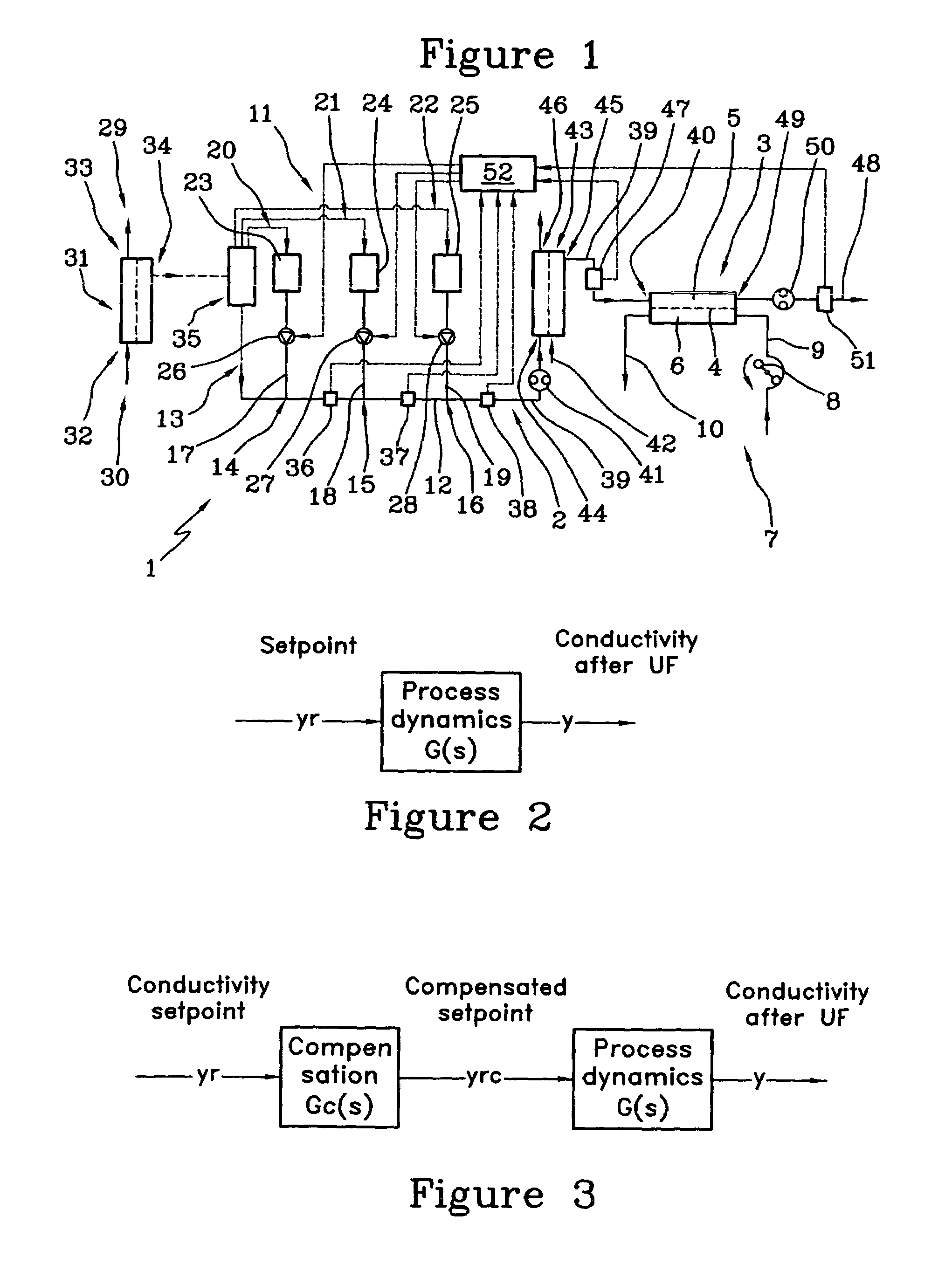
[0031]According to an embodiment of the invention, said mathematical model is selected so as said altering function comprises a dynamic compensation that takes into account the process dynamics of said apparatus portion in order to reduce the settling time of said response.
[0032]According to an embodiment of the invention, the mathematical model comprises an inverse of a transfer function that describes how the second liquid characteristic changes in response to an alteration of the first liquid characteristic. The order of the transfer function may be one or greater than one.

Problems solved by technology

A large filter in the dialysis line creates an extra time period for stabilizing the outlet conductivity after the dialyzer, this extra delay in the response created by the clean dialysate filter being on top of the delay already created by the dialyzer, whereby 2 minutes may no longer be sufficient to allow reliable results.
One immediate disadvantage is that the mean conductivity in the inlet fluid will be changed, especially if, as normal, measurements are performed every 15 or 30 minutes.
The treatment would no longer be performed with essentially constant conductivity, and the prescribing doctor might view this as a limitation.
Another disadvantage arises when the above-described monitoring system is combined with conductivity profiling, since profiling has to be prevented during and around the conductivity step increment very little time would be left for conductivity profiling.

Method used


Image

  • Method and apparatus for determining a patient or treatment or apparatus parameter during an extracorporeal blood treatment
  • Method and apparatus for determining a patient or treatment or apparatus parameter during an extracorporeal blood treatment
  • Method and apparatus for determining a patient or treatment or apparatus parameter during an extracorporeal blood treatment

Examples


examples

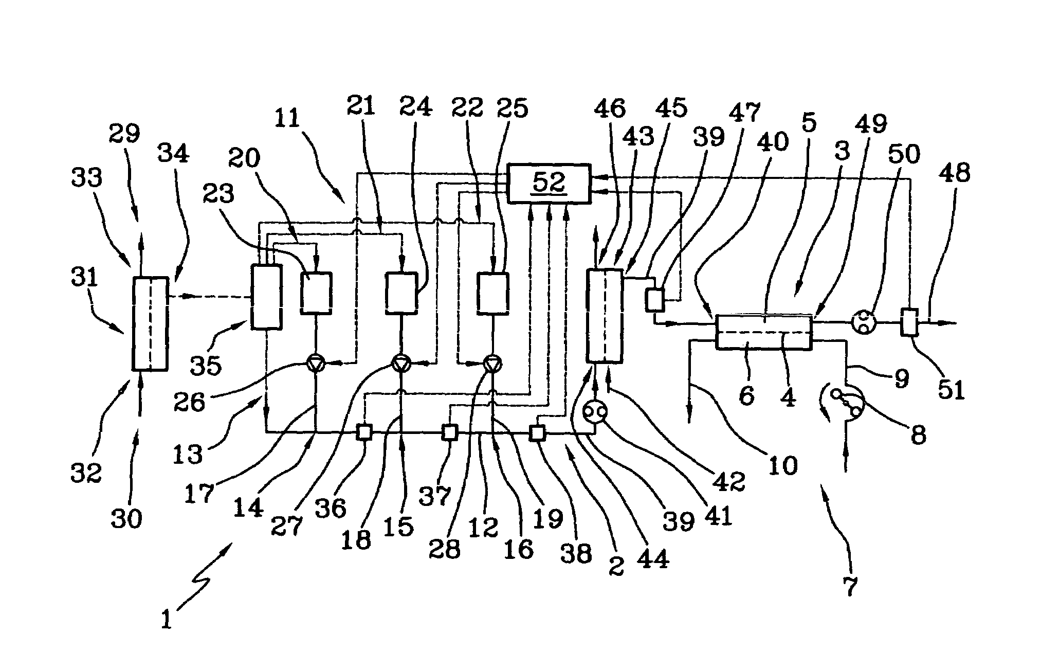
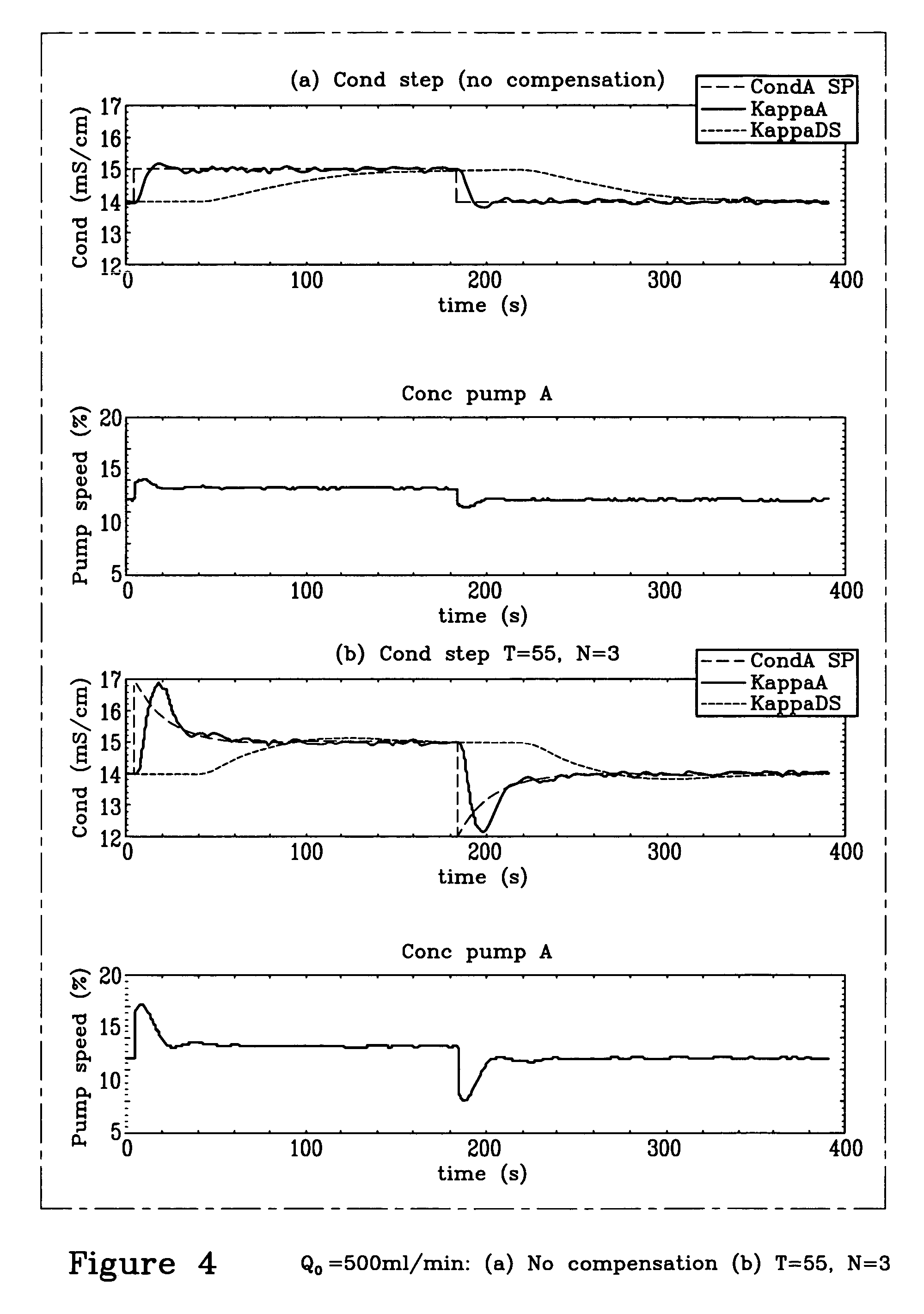
[0176]In these examples a dynamic first order compensation of the set alteration has been used to speed up the conductivity response in the HDF / HF apparatus of FIG. 1 which has a clean dialysate filter (ultrafilter).

[0177]The first liquid was the fresh dialysis liquid before the clean dialysate filter and the second liquid was the cleaned fresh dialysis liquid after the clean dialysate filter and before the dialyzer.

[0178]A test was performed on the apparatus of FIG. 1 based on the following system parameter settings:

[0179]

Degassing pressure:100 mmHg (abs)Dialysate main flow:300 / 500 / 900 ml / minTcA dialysate temperature set value:37° C.

[0180]Conductivity set value at measurement device 36 3.1 mS / cm [after HCO3 infusion point 14]=34 mmol / l

[0181]Conductivity set value at measurement device 37 3.1 mS / cm (concentrated solution 24 not used)

[0182]Conductivity set value at measurement device 38 14 mS / cm [after Na infusion point 16]=approx. 140 mmol / l

[0183]Conductivity Step amplitude 1 mS / cm

[...


PUM

PropertyMeasurementUnit
conductivityaaaaaaaaaa
time constantaaaaaaaaaa
conductivityaaaaaaaaaa

Abstract

During a dialysis treatment carried out by a dialysis apparatus, in which a dialysis liquid is circulated to a clean dialysate filter (43) arranged before a dialyser (3), the conductivity of the dialysis liquid is altered according to an altering function that is a function of a mathematical model of the filter (43), in a way that will make the conductivity after the filter change more quickly. A conductivity cell (47), which is arranged after the dialyser, measures the conductivity of the spent dialysis liquid changed in response to said alteration. A control and computer system (52) evaluates the dialysance from said measured response. The conductivity can be changed for a comparatively short time period that is sufficient to allow reliable results.

Description

CROSS REFERENCE TO RELATED APPLICATION[0001]This application claims the benefit of U.S. Provisional Application No. 60 / 531,280, filed on Dec. 18, 2003, the contents of which are incorporated herein by reference.BACKGROUND OF THE INVENTION[0002]The invention relates to a method and to an apparatus for determining at least one patient or treatment or apparatus parameter during an extracorporeal blood treatment carried out in an extracorporeal blood treatment apparatus.[0003]Specifically, though not exclusively, the invention can be usefully applied in dialysis treatments.[0004]The parameters to be determined can be, for example, ionic dialysance or clearance, plasma conductivity, plasma sodium concentration, dialysis dose, depurated volume of patient body water, ionic mass balance, blood recirculation, fistula flow, etc.[0005]During a dialysis treatment, it is desirable to monitor patient or treatment or apparatus parameters in order, for example, to provide a measure of treatment eff...

Claims


Application Information

Patent Timeline
Patent Type & Authority Patents(United States)
IPC IPC(8): B01D61/00B01D61/24B01D61/30B01D61/32A61M1/16
CPCA61M1/16A61M1/1617A61M1/1609A61M1/1607A61M2205/3317A61M2205/3324A61M1/1613
Inventor STERNBY, JAN PETER
Owner GAMBRO LUNDIA AB
Learn More