Radar detection and dynamic frequency selection

a dynamic frequency selection and radar detection technology, applied in the field of radar systems, can solve problems such as false detection of radar on a channel, interference between publicly used wireless networks and military radar systems, and wireless network signals may interfere with military radar communications

Active Publication Date: 2010-04-20
MARVELL ASIA PTE LTD
View PDF6 Cites 117 Cited by
  • Summary
  • Abstract
  • Description
  • Claims
  • Application Information

AI Technical Summary

Problems solved by technology

As a result, wireless network signals may interfere with military radar communications.
Interference between publicly used wireless networks and military radar systems is undesirable for security reasons.
Some network devices, however, may falsely detect radar on a channel.
The network will unnecessarily block the channel despite the fact that the detected signal is not a radar signal.
As false detections increase, additional channels may be blocked and fewer channels will remain available for network communications.
This can significantly degrade network performance.

Method used


Image

  • Radar detection and dynamic frequency selection
  • Radar detection and dynamic frequency selection
  • Radar detection and dynamic frequency selection

Examples


Embodiment Construction

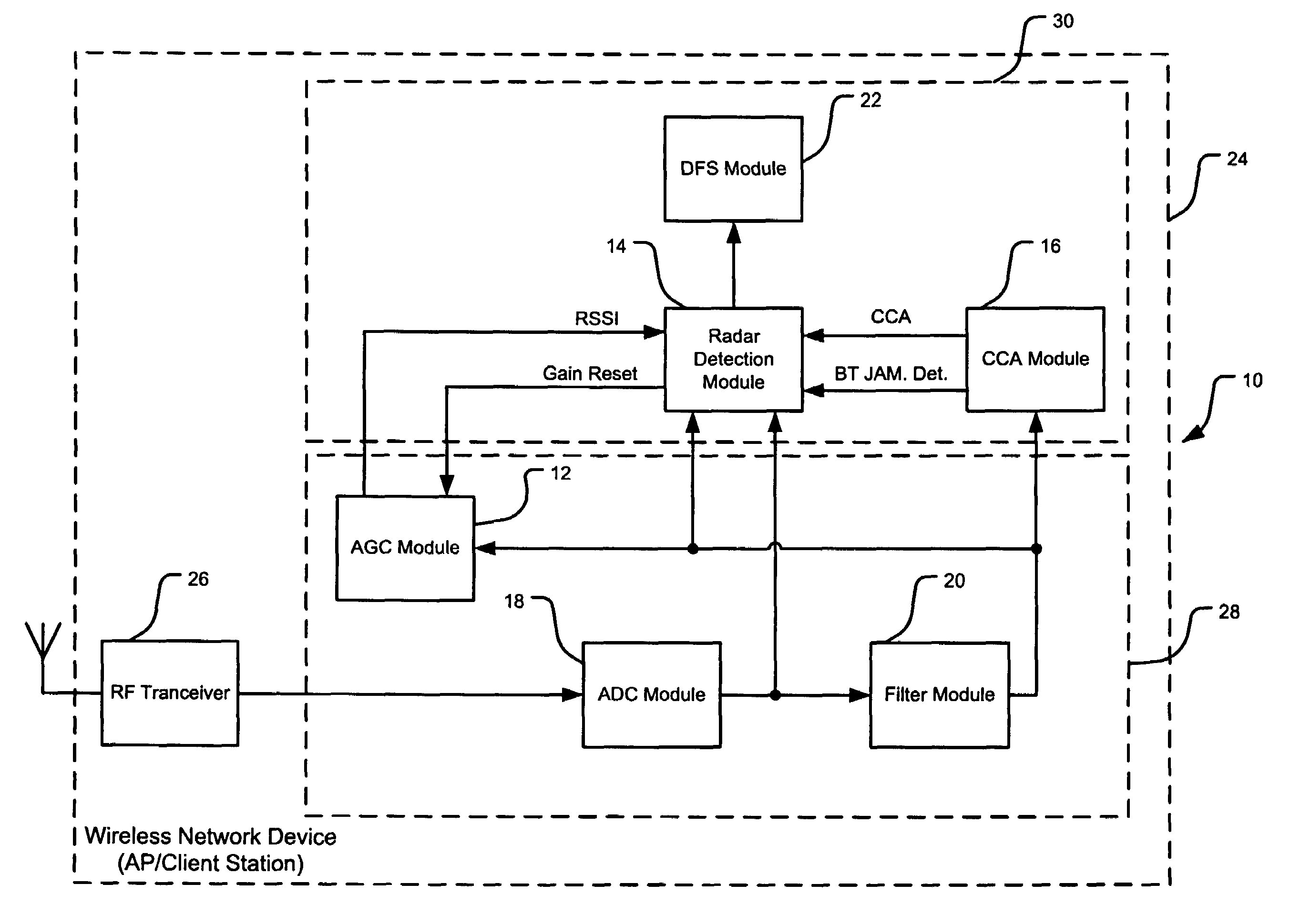
[0066]The following description of the preferred embodiment(s) is merely exemplary in nature and is in no way intended to limit the invention, its application, or uses. For purposes of clarity, the same reference numbers will be used in the drawings to identify similar elements. As used herein, the term module, circuit and / or device refers to an Application Specific Integrated Circuit (ASIC), an electronic circuit, a processor (shared, dedicated, or group) and memory that execute one or more software or firmware programs, a combinational logic circuit, and / or other suitable components that provide the described functionality. As used herein, the phrase at least one of A, B, and C should be construed to mean a logical (A or B or C), using a non-exclusive logical or. It should be understood that steps within a method may be executed in different order without altering the principles of the present invention.

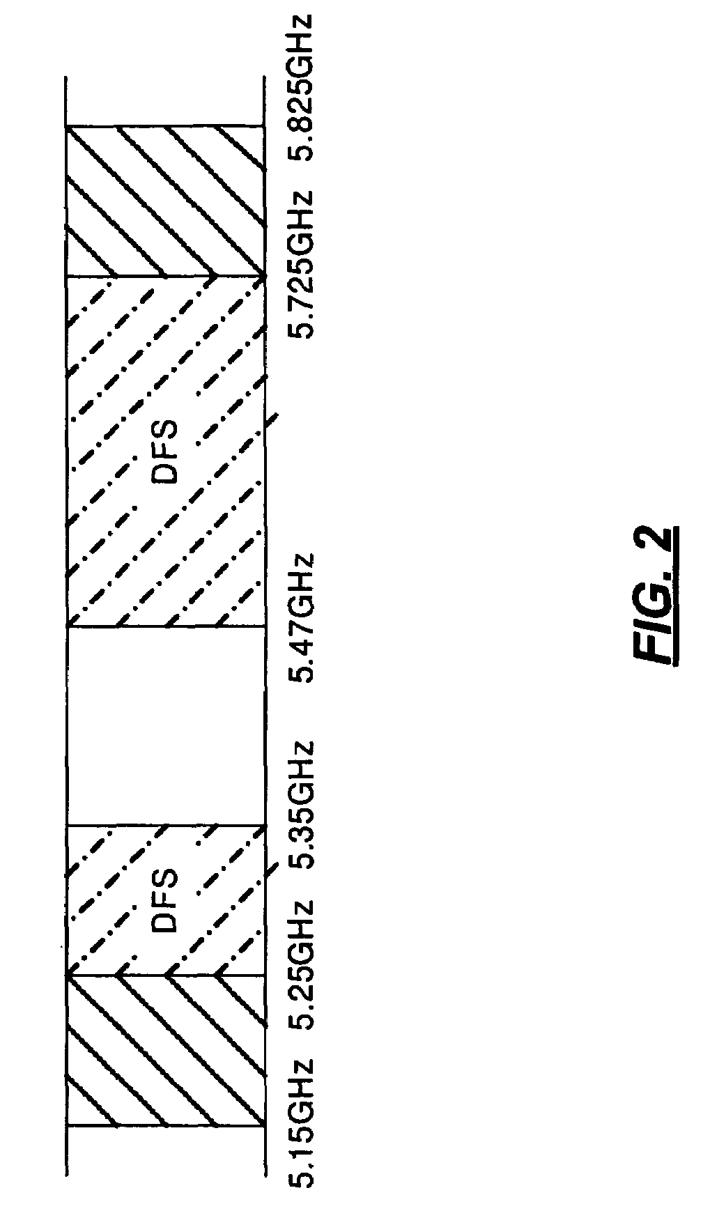
[0067]Referring now to FIG. 2, dynamic frequency selection (DFS) is used to av...


PUM


Abstract

A wireless network device includes a correlation module, an automatic gain control module, and a control module. The correlation module correlates a predetermined portion of a radio frequency (RF) signal and generates a correlation signal based thereon. The automatic gain control (AGC) module generates a gain control signal based on said RF signal. The control module selectively determines whether said RF signal is a radar signal based on said correlation signal and said gain control signal.

Description

CROSS-REFERENCE TO RELATED APPLICATIONS[0001]This application claims the benefit of U.S. Provisional Application No. 60 / 742,480, filed on Dec. 5, 2005. The disclosure of the above application is incorporated herein by reference in its entirety.FIELD OF THE INVENTION[0002]The present invention relates to radar systems, and more particularly to radar detection algorithms.BACKGROUND OF THE INVENTION[0003]Radar is an acronym for Radio Detection and Ranging. The term “radio” refers to a radio frequency (RF) wave called a carrier of frequency fc that is modulated to form a radar pulse train. The detection and ranging part of the acronym refers to timing a delay between transmission of an RF pulse and its subsequent return. If the time delay is Δt, a range of the radar may be determined by the formula:R=cΔt / 2where c=3×10⁸ m / s and is the speed of light. The factor of two in the formula accounts for the return trip.[0004]Referring now to FIG. 1, a radar burst comprises a plurality of radar p...

Claims


Application Information

Patent Timeline
Patent Type & Authority Patents(United States)
IPC IPC(8): H03D1/00H04L27/06
CPCG01S7/023G01S7/021G01S7/0232G01S13/04
Inventor NALLAPUREDDY, BHASKAR V.YU, TSUNGLUNHSU, YUNGPINGNENG, SEK KIN
Owner MARVELL ASIA PTE LTD
Why Eureka
Try Eureka