Monitoring a local area network

a local area network and monitoring technology, applied in data switching networks, frequency-division multiplexes, instruments, etc., can solve problems such as difficult diagnosis of the cause of connectivity problems, unauthenticated stations, and unassociated stations

Inactive Publication Date: 2010-04-20
AIRMAGNET
View PDF41 Cites 36 Cited by
  • Summary
  • Abstract
  • Description
  • Claims
  • Application Information

AI Technical Summary

Problems solved by technology

In State 1, the station is unauthenticated and unassociated.
If a station has a connectivity problem, such as d...

Method used


Image

  • Monitoring a local area network
  • Monitoring a local area network
  • Monitoring a local area network

Examples


Embodiment Construction

[0017]In order to provide a more thorough understanding of the present invention, the following description sets forth numerous specific details, such as specific configurations, parameters, examples, and the like. It should be recognized, however, that such description is not intended as a limitation on the scope of the present invention, but is intended to provide a better description of the exemplary embodiments.

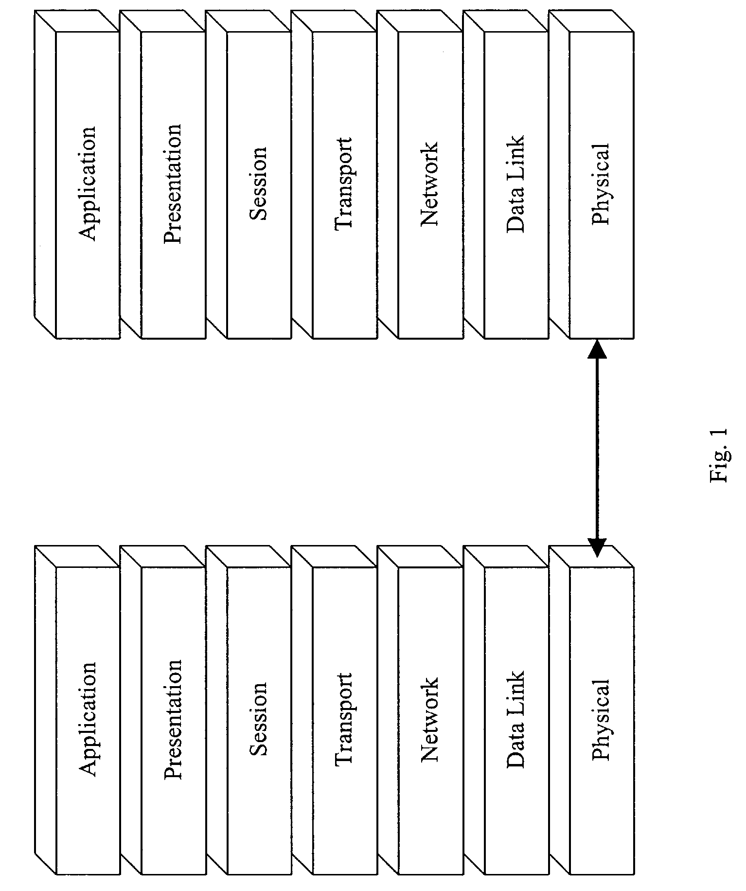
[0018]With reference to FIG. 1, an exemplary Open Systems Interconnection (OSI) seven layer model is shown, which represents an abstract model of a networking system divided into layers according to their respective functionalities. In particular, the seven layers include a physical layer corresponding to layer 1, a data link layer corresponding to layer 2, a network layer corresponding to layer 3, a transport layer corresponding to layer 4, a session layer corresponding to layer 5, a presentation layer corresponding to layer 6, and an application layer corresponding to l...


PUM


Abstract

A wireless local area network (WLAN) is monitored by receiving transmissions exchanged between one or more stations and an access point (AP) in the WLAN using a detector located in the WLAN. A database is compiled based on the received transmissions. The received transmissions are analyzed to determine the state of a station. The compiled database and the determined state of the station are used to diagnose connectivity problems of the station.

Description

CROSS REFERENCE TO RELATED APPLICATION[0001]This application claims the benefit of an earlier filed provisional application U.S. Provisional Application Ser. No. 60 / 371,084, entitled MONITORING A LOCAL AREA NETWORK, filed on Apr. 8, 2002, the entire content of which is incorporated herein by reference.BACKGROUND[0002]1. Field of the Invention[0003]The present invention generally relates to wireless local area networks. More particularly, the present invention relates to monitoring a wireless local area network.[0004]2. Description of the Related Art[0005]Computers have traditionally communicated with each other through wired local area networks (“LANs”). However, with the increased demand for mobile computers such as laptops, personal digital assistants, and the like, wireless local area networks (“WLANs”) have developed as a way for computers to communicate with each other through transmissions over a wireless medium using radio signals, infrared signals, and the like.[0006]In orde...

Claims


Application Information

Patent Timeline
IPC IPC(8): G06F15/173H04B7/26H04L12/26H04L12/28H04L12/56H04L29/06H04W8/22H04W8/26H04W12/06H04W24/00H04W84/12H04W88/08
CPCH04L12/26H04L43/0811H04L63/08H04L63/10H04L63/1408H04L63/162H04W8/26H04W12/06H04W12/12H04W24/00H04L43/00H04W88/08H04L43/0847H04L43/12H04L43/16H04W8/22H04W84/12H04L12/28H04W24/08H04J3/16H04L12/06
Inventor KUAN, CHIA-CHEEWU, MILESAU, DEAN
Owner AIRMAGNET
Why Eureka
Try Eureka