Supercharging system for two-stage supercharging of V-type internal combustion engines

a technology of internal combustion engine and supercharging system, which is applied in the direction of combustion engine, internal combustion piston engine, machine/engine, etc., can solve the problems of short exhaust gas pipeline, and achieve the effect of reducing the loss of pressure, and reducing the amount of exhaust gas

Inactive Publication Date: 2010-04-27
ROBERT BOSCH GMBH
View PDF11 Cites 21 Cited by
  • Summary
  • Abstract
  • Description
  • Claims
  • Application Information

AI Technical Summary

Benefits of technology

[0009]The charge air cooler may be accommodated in a particularly advantageous manner in the area of a wheel box in the engine compartment. In the case of a two-stage supercharging system having no intermediate cooling, two charge air coolers are employed which are used for final cooling of the fresh air precompressed in the low pressure compressor and in the high pressure compressor before entering the combustion chambers of the internal combustion engine. In this embodiment variant, both charge air coolers may be parallel-connected in a particularly advantageous manner, which enables the pressure loss to be minimized on the fresh air side. Bypass valves may be used to cut off the flow through the two charge air coolers when, for example, the high pressure compressor is in use, and the pressure may be built up faster thereby due to smaller container volumes. According to the embodiment variant of the two-stage supercharging system having no intermediate cooling, the two exhaust gas turbochargers may also be positioned to the left and right of the internal combustion engine. The exhaust gas manifolds of the internal combustion engine are connectable to each other via a common exhaust gas line.
[0010]According to a preferred embodiment of the above-outlined embodiment variant of the supercharging system according to the present invention for internal combustion engines having V-shaped cylinder bank layouts or designed as flat engines, the supercharging systems are connected to the relevant cylinder bank as far to the front or rear as possible, i.e., viewed in relation to the direction of vehicle travel, on an end face of the engine (in front) or a back end of the engine (in the rear). This results in short exhaust gas pipes leading to the cylinder banks, and minimal flow losses as a consequence thereof, as well as an end-face surface that dissipates little heat. In a preferred embodiment with regard to the efficiency of the overall system, a thermally insulated design of the exhaust gas system, in particular of connecting lines, is provided, using air gap insulated pipes between the supercharging systems and the cylinder banks. The design according to the present invention supports the shortest possible connecting pipes so that the flow losses may be kept within narrow limits.

Problems solved by technology

This results in short exhaust gas pipes leading to the cylinder banks, and minimal flow losses as a consequence thereof, as well as an end-face surface that dissipates little heat.

Method used


Image

  • Supercharging system for two-stage supercharging of V-type internal combustion engines
  • Supercharging system for two-stage supercharging of V-type internal combustion engines
  • Supercharging system for two-stage supercharging of V-type internal combustion engines

Examples


Embodiment Construction

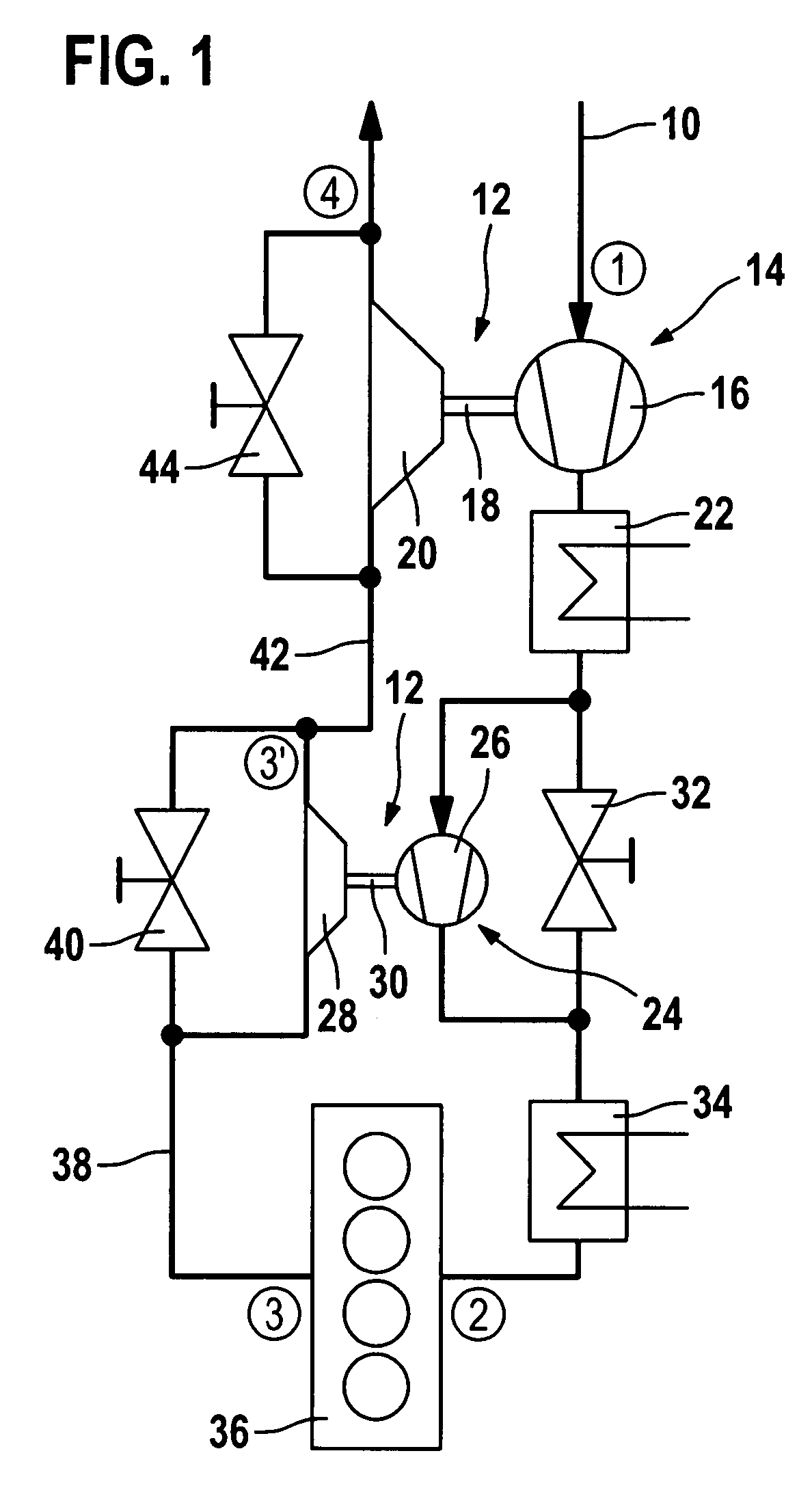
[0014]The illustration according to FIG. 1 shows a schematic flow chart of a regulated two-stage supercharging system.

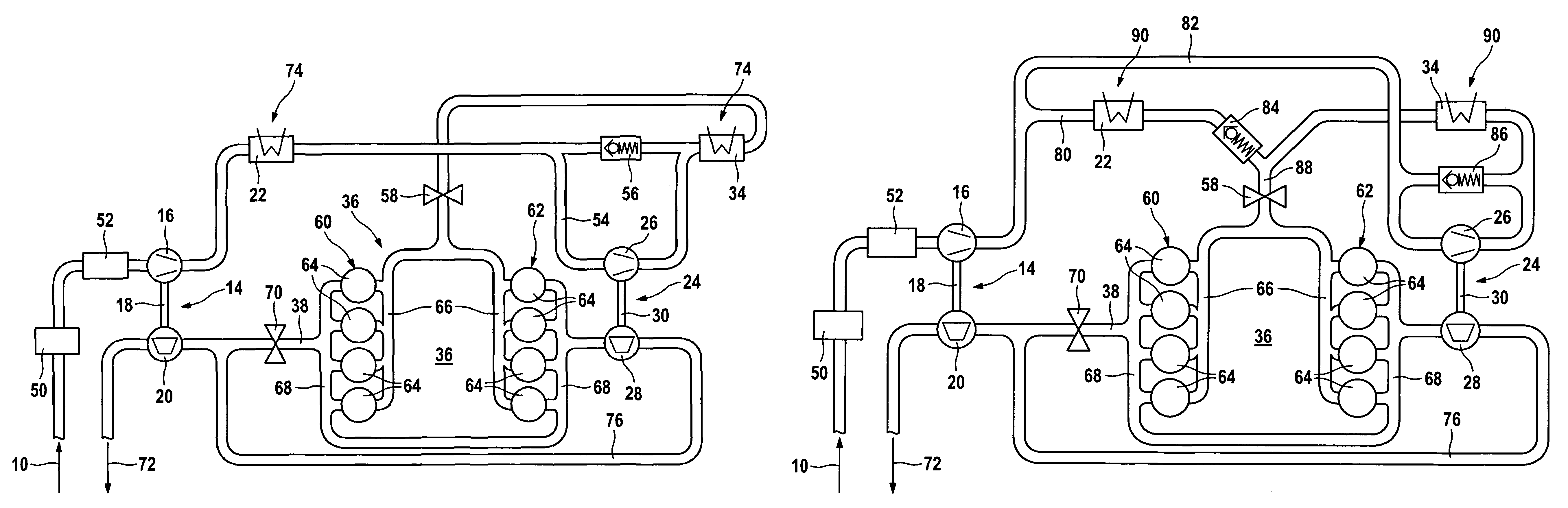
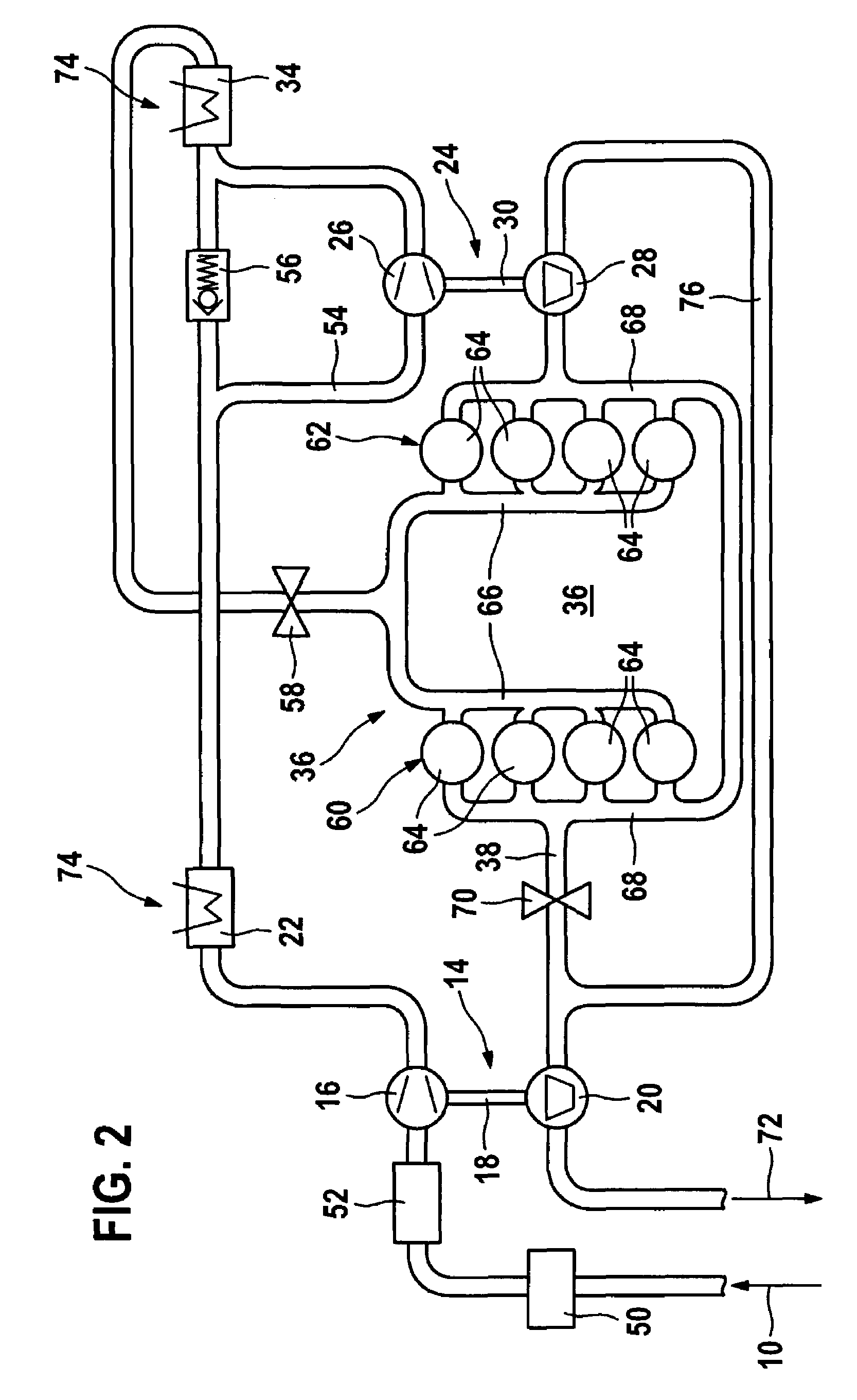
[0015]According to the illustration in FIG. 1, a two-stage supercharging system 12 has a first exhaust gas turbocharger 14 and a second exhaust gas turbocharger 24. Fresh air 10, which has a state (1), is compressed via a low pressure compressor part 16 of first exhaust gas turbocharger 14. The precompressed fresh air is cooled in a first charge air cooler 22 connected downstream from low pressure compressor part 16 of first exhaust gas turbocharger 14. In addition to low pressure compressor part 16, first exhaust gas turbocharger 14 also includes a low pressure turbine part 20 which is coupled with low pressure compressor part 16 via a shaft. After passing through first charge air cooler 22, the precompressed fresh air flows to a high pressure compressor part 26 of a second exhaust gas turbocharger 24. High pressure compressor part 26 of second exhaust gas turbochar...


PUM


Abstract

A supercharging system, in particular an at least two-stage supercharging system, including a first stage and a second stage for an internal combustion engine having two cylinder banks. The at least two-stage supercharging system includes at least two charge air coolers. An exhaust gas turbocharger representing the first stage and an exhaust gas turbocharger representing the second stage are each situated next to one of the cylinder banks of the internal combustion engine.

Description

BACKGROUND INFORMATION[0001]The power limits of a supercharging system such as an exhaust gas turbocharger are increased, for example by regulated two-stage supercharging, as is known from Bosch, Kraftfahrtechnisches Taschenbuch [Automotive Handbook], 23rd Edition, Vieweg, 1999, pages 445 through 446. In regulated two-stage supercharging, two exhaust gas turbochargers of different sizes are connected in series. The exhaust gas mass flow first flows into an exhaust gas manifold. From there, the exhaust gas mass flow is expanded via a high pressure turbine. In the case of large exhaust gas volumes, which can occur at high speeds, a portion of the exhaust gas mass flow may be redirected around the high pressure turbine via a bypass. The entire exhaust gas mass flow is subsequently used by a low pressure turbine connected downstream from the high pressure turbine. The incoming fresh air mass flow is first precompressed by a low pressure stage and then further compressed in the high pres...

Claims


Application Information

Patent Timeline
Patent Type & Authority Patents(United States)
IPC IPC(8): F02B33/44F01N1/00F02B37/00F02B37/013F02B37/007F02B29/04F02B33/00
CPCF01N13/143F02B29/0412F02B29/0418F02B37/001F02B37/002F02B37/013F02B37/02F02B37/127F02B37/18F02B37/004F01N13/107Y02T10/144F02B75/22Y02T10/146F02B37/162Y02T10/12
Inventor BECKER, BODOVOGT, GUENTHERCOCCA, OLIVER
Owner ROBERT BOSCH GMBH
Why Eureka
Try Eureka