Process for producing patterned optical filter layers on substrates

Active Publication Date: 2010-04-27
SCHOTT AG
View PDF32 Cites 40 Cited by
  • Summary
  • Abstract
  • Description
  • Claims
  • Application Information

AI Technical Summary

Benefits of technology

[0059]According to yet another embodiment of the invention, it is provided that a segment of the surface in the shape of a segment of a circle be coated with an optical filter layer. This type of shape of a filter segment is advantageous in particular in the case of rotating optical filters, for example in the case of a disk-like substrate for a color wheel, as used, for example, in a digital projector.
[0060]One further possibility is, inter alia, the deposition of an optical filter layer segment which is shaped in the form of a visible item of information, in particular lettering, a symbol or a logo. Consequently, the invention also allows decorative or marking effects to be achieved.

Problems solved by technology

It has been found that the standard removal of the resist layer by dissolving it may cause problems after high thermal loads during the vacuum deposition of the layer.

Method used


Image

  • Process for producing patterned optical filter layers on substrates
  • Process for producing patterned optical filter layers on substrates
  • Process for producing patterned optical filter layers on substrates

Examples


Embodiment Construction

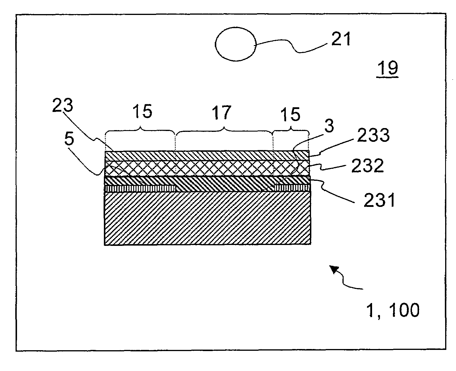
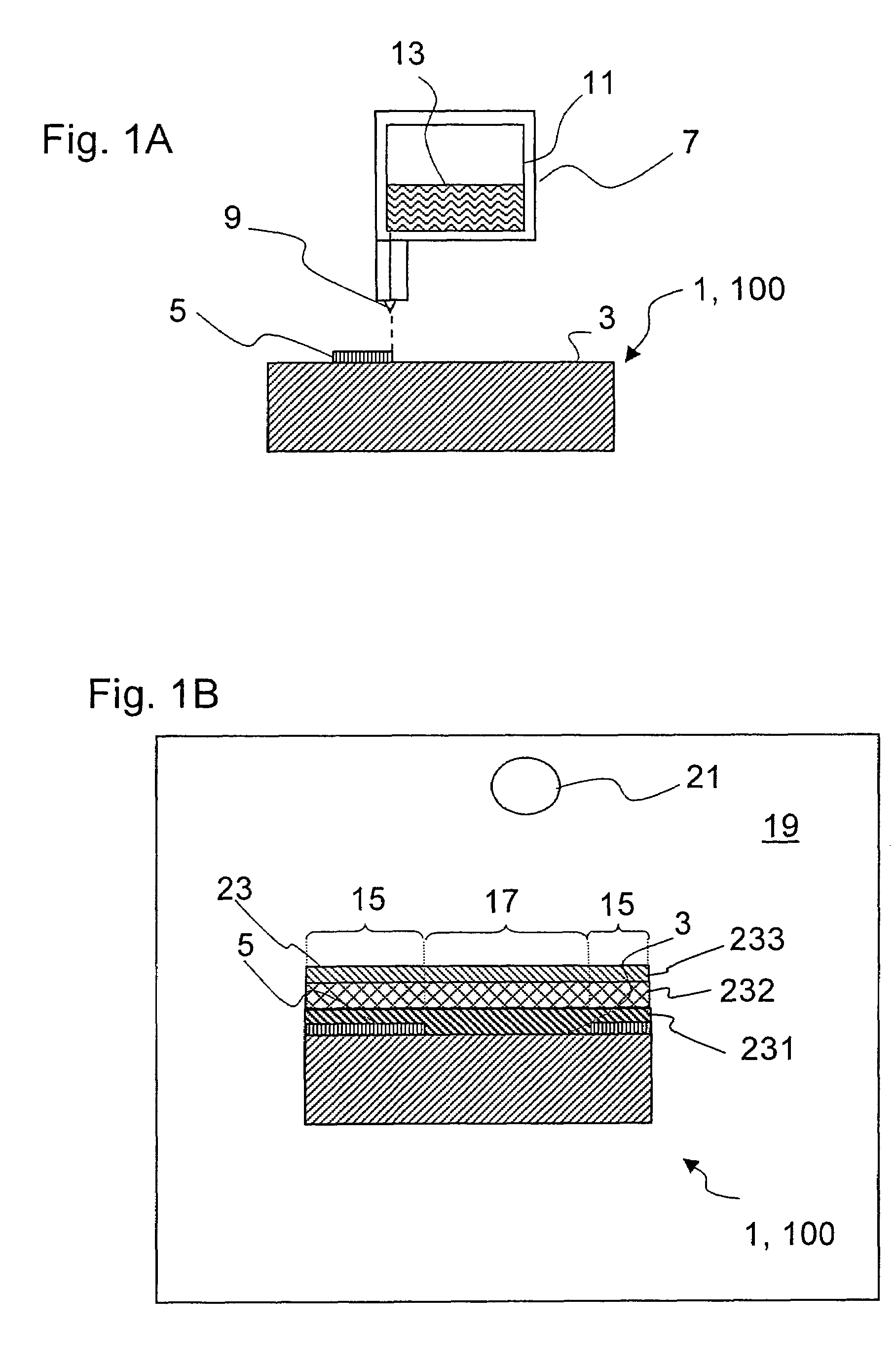
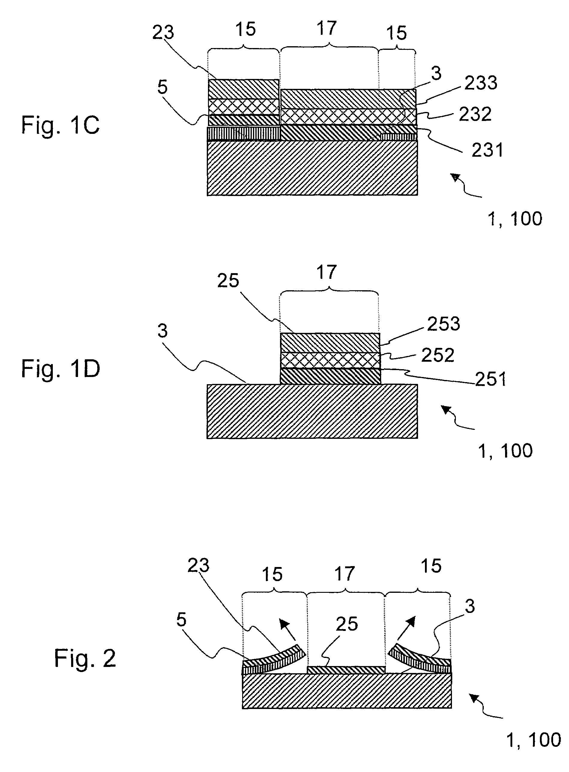
[0072]Process steps involved in the production of a substrate 1 which has been coated in accordance with a first embodiment of the invention are shown with reference to FIGS. 1A to 1D, which diagrammatically depict cross-sectional views of a substrate 1.

[0073]The process for producing a substrate 1 with one or more optical filter layer segments is based on the fact that[0074]a masking comprising a resist layer is produced on a surface 3 of the substrate 1,[0075]an optical filter layer is deposited on the surface by vacuum deposition, and[0076]the resist layer with the optical filter layer thereon is removed by causing the resist layer to swell.

[0077]According to this first embodiment of the invention, which is shown in FIG. 1A to 1D, the substrate 1 is masked with a resist layer 5 by the application of a resist 13, the application of the resist 13 in particular being computer-controlled via the nozzles 9 of a print head 7 which is connected to a computer (not shown in FIG. 1A). A pr...


PUM

PropertyMeasurementUnit
temperatureaaaaaaaaaa
temperaturesaaaaaaaaaa

Abstract

The invention provides a process for producing at least one optical filter layer segment on a substrate. The process includes
    • applying a masking comprising a resist layer on a surface of the substrate,
    • depositing an optical filter layer on the surface and the resist layer by vacuum deposition, and
    • removing the resist layer with a portion of the optical filter layer thereon from the surface.
The deposition of the optical filter layer, at least at times, takes place at a temperature of over 150° C., preferably in a range from over 150° C. up to and including 400° C.

Description

CROSS-REFERENCES TO RELATED APPLICATIONS[0001]The present application is claiming priority of German Patent Application No. 10 2004 034418.3-51, filed on Jul. 15, 2004, the content of which is herein incorporated by reference.BACKGROUND OF THE INVENTION[0002]1. Field of the Invention[0003]The invention relates in general terms to the production of patterned optical coatings on substrates; in particular, the invention relates to the production of areally patterned, in particular segmented optical filter layers on substrates.[0004]2. Description of Related Art[0005]Areally segmented optical coatings on substrates are required, inter alia, for optical filters, such as for example optical rotary filters or color wheels for video projectors. A filter of this type sequentially filters light rays of different colors out of a light beam and projects them onto a screen by means of a digital micromirror device (DMD).[0006]For the sequential filtering, a color wheel of this type is divided int...

Claims


Application Information

Patent Timeline
Patent Type & Authority Patents(United States)
IPC IPC(8): G03F7/00G02B5/20
CPCC23C14/0005C23C14/042G02B5/201C23C16/515C23C16/042
Inventor WITTENBERG, DIETERKUEPPER, THOMASZOGG, LUTZMEHRTENS, ANDREE
Owner SCHOTT AG
Why Eureka
Try Eureka