Capacitor power source and charging/discharging control apparatus therefor

a technology of capacitor power source and control apparatus, which is applied in the direction of electric power, electric vehicles, transportation and packaging, etc., can solve the problems of adversely affecting the life of the capacitor, the capacitor itself becoming deteriorated, and the inability to obtain a sufficiently large electrostatic capacity, etc., to achieve stable use and long-time use, improve charging performance, and large electrostatic capacity

Inactive Publication Date: 2010-04-27
POWER SYST KK
View PDF6 Cites 12 Cited by
  • Summary
  • Abstract
  • Description
  • Claims
  • Application Information

AI Technical Summary

Benefits of technology

[0008]An object of the present invention is to perform charging / discharging operation for an electric double layer capacitor in which charging / discharging characteristics at a constant current becomes larger in a low voltage region relative to the voltage change rate in a high voltage region within a range within which a large electrostatic capacity can be obtained but the life of the capacitor is not adversely affected to thereby effectively use the region in which the electrostatic capacity becomes large.
[0015]According to the present invention, it is possible to effectively use an electric double layer capacitor within a voltage range in which a large electrostatic capacity can be developed without being deteriorated. Further, charging / discharging operation is not performed in the low voltage region in which an electrostatic capacity is small but in the high voltage region repeatedly, improving charging performance to a maximum extent, allowing stable use and long-time use, and reducing the fluctuation range of the voltage in a charging / discharging circuit. Thus, it is possible to reduce the load and waste of a control circuit which is generated in a circuit having a large fluctuation range of the voltage.

Problems solved by technology

Thus, even if this electric double layer capacitor is used against reason, not only it is impossible to obtain a sufficiently large electrostatic capacity but also the capacitor itself becomes deteriorated.
As described above, a charging / discharging cycle in which the depth of discharge falls below the inflection-point voltage adversely affects the life of the capacitor.

Method used


Image

  • Capacitor power source and charging/discharging control apparatus therefor
  • Capacitor power source and charging/discharging control apparatus therefor
  • Capacitor power source and charging/discharging control apparatus therefor

Examples


Embodiment Construction

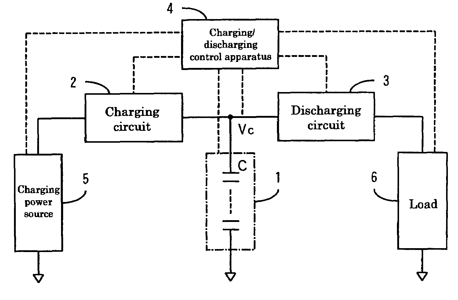
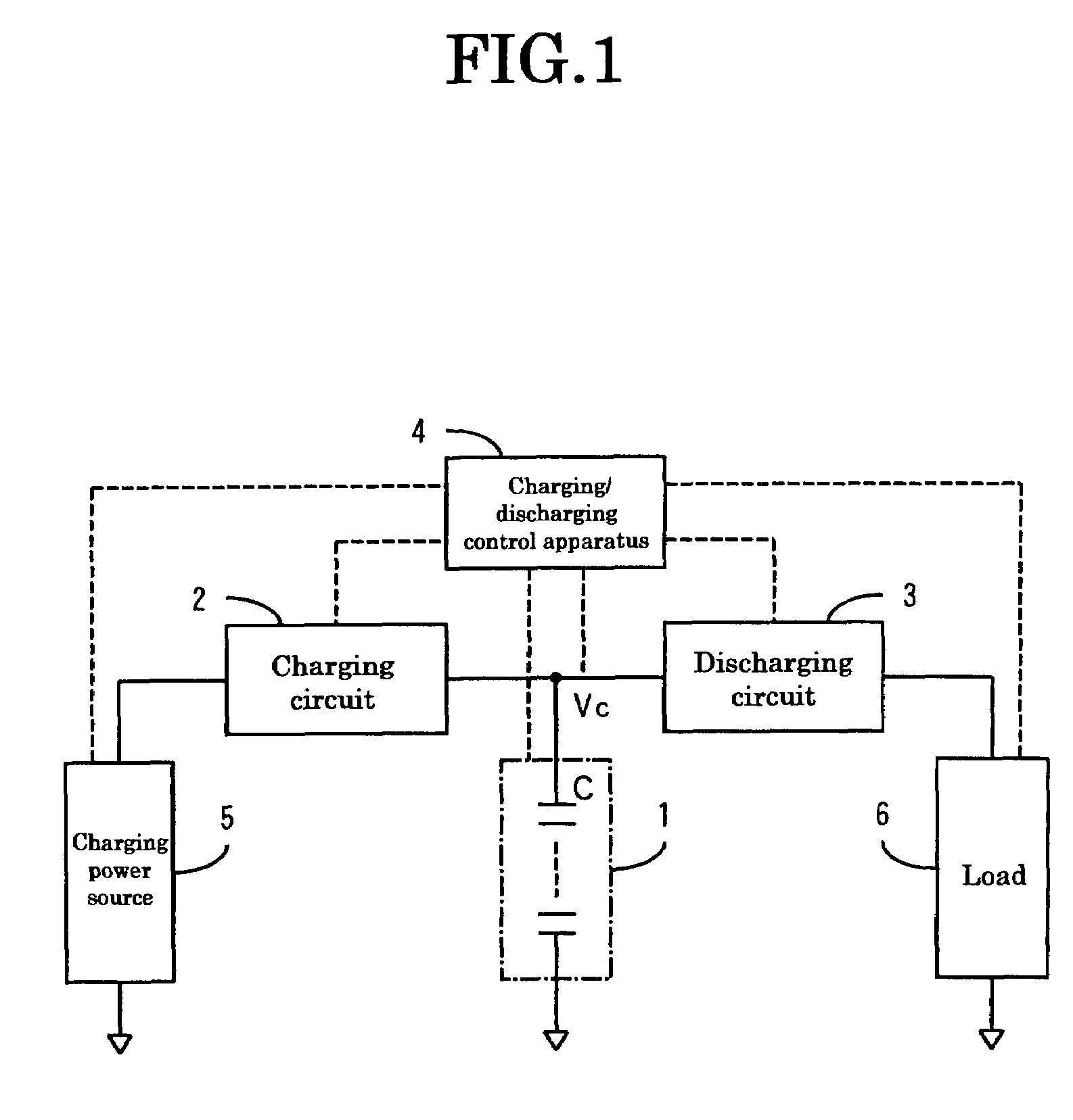
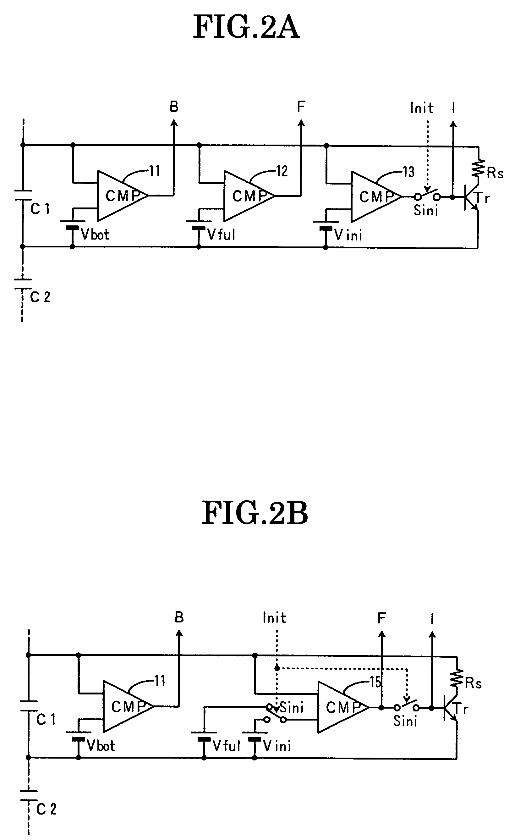
[0030]An embodiment of the present invention will be described below with reference to the accompanying drawings. FIG. 1 is a view explaining an embodiment of a capacitor power source and a charging / discharging control apparatus therefor according to the present invention. FIGS. 2A and 2B are views each showing an embodiment of a capacitor including an inflection-point voltage detection circuit, an overvoltage detection circuit, and an initialization circuit. FIGS. 3A to 3D are views each showing an embodiment of a signal processing circuit for performing charging control. In the drawings, 1 is a capacitor power source, 2 is a charging circuit, 3 is a discharging circuit, 4 is a charging / discharging control apparatus, 5 is a charging power source, 6 is a load, 11 to 15 and 43 are comparison circuits, 41 and 42 are OR gates, 44 is an AND gate, As is an analog switch, B is a detection signal of an inflection-point voltage, F is a detection signal of an overvoltage, I is a bypass opera...


PUM


Abstract

A capacitor power source 1 including a plurality of capacitors comprises: an inflection-point voltage detection circuit (11) for detecting the inflection-point voltage of the capacitor based on a set voltage Vbot; an overvoltage detection circuit (12) for detecting the overvoltage Vful of the capacitor;and an initialization circuit (13) for putting charging current of the capacitor into bypass operation using initialization voltage Vini when an initialization mode is selected, wherein charging / discharging control is performed such that a discharging stop signal is generated based on a detection signal of the inflection-point voltage of any one of the plurality of capacitors, a charging stop signal is generated based on a detection signal of the overvoltage of any one of the plurality of capacitors, and an end signal of the initialization charging is generated based on a plurality of bypass operation signals.

Description

CROSS REFERENCES TO RELATED APPLICATIONS[0001]This application is based upon and claims the benefit of priority from prior Japanese Patent Application No. 2006-154221, filed Sep. 5, 2006, the entire contents of which are incorporated herein by reference.BACKGROUND OF THE INVENTIONField of the Invention[0002]The present invention relates to a capacitor power source including a plurality of capacitors each having curved charging / discharging characteristics in which a voltage change rate resulting from constant current charging / discharging operation becomes smaller in a high voltage region than that in a low voltage region on reaching the vicinity of the inflection-point voltage and various circuits provided for the plurality of capacitors, including an inflection-point voltage detection circuit for detecting an inflection-point voltage based on a set voltage, an overvoltage detection circuit for detecting an overvoltage, and an initialization circuit for putting charging current into ...

Claims


Application Information

Patent Timeline
Patent Type & Authority Patents(United States)
IPC IPC(8): H02J7/00H02J7/02
CPCH02J7/345
Inventor OKAMURA, MICHIOSHIMIZU, ATSUSHI
Owner POWER SYST KK
Why Eureka
Try Eureka