
Voltage detecting apparatus

a technology of voltage detection and detecting device, which is applied in the direction of impedence measurement, instruments, measurement devices, etc., can solve the problems of increasing the cost and a size of the circuit, the limitation of the miniaturization of the apparatus, and the increase in the cost of the circuit, so as to achieve the elimination of the elongated measurement time in normal condition, the effect of enlarged component sizes and enlarged components

Inactive Publication Date: 2010-04-27
YAZAKI CORP
View PDF4 Cites 3 Cited by
  • Summary
  • Abstract
  • Description
  • Claims
  • Application Information

AI Technical Summary

Benefits of technology

The present invention provides a voltage detecting apparatus that can process an abnormal voltage without increasing the cost or size of the circuit. The apparatus uses a reset circuit and a plurality of reset switches to discharge the capacitor in a normal condition. The apparatus includes a direct-current power source, a capacitor, a voltage measuring unit, and a switch controller for selectively controlling the reset switches. The switch controller selectively controls the reset switches based on a predetermined value to gradually discharge the capacitor and achieve a normal condition. The apparatus can detect abnormal voltages and discharge the capacitor quickly, without increasing the measuring time in the normal condition. The resistance value of the reset switch is set so that the current flowing through the reset switch is always less than the maximum rated current, which eliminates the need for a margin in the abnormal voltage condition. The apparatus can be designed more efficiently and cost-effectively.

Problems solved by technology

For designing the circuit having the flowing current margin against the flowing current in the normal condition, components used in the circuit become more expensive and then a cost and a size of the circuit will increase, with the result that miniaturization of the apparatus is limited.

Method used


Image

  • Voltage detecting apparatus
  • Voltage detecting apparatus
  • Voltage detecting apparatus

Examples


Embodiment Construction

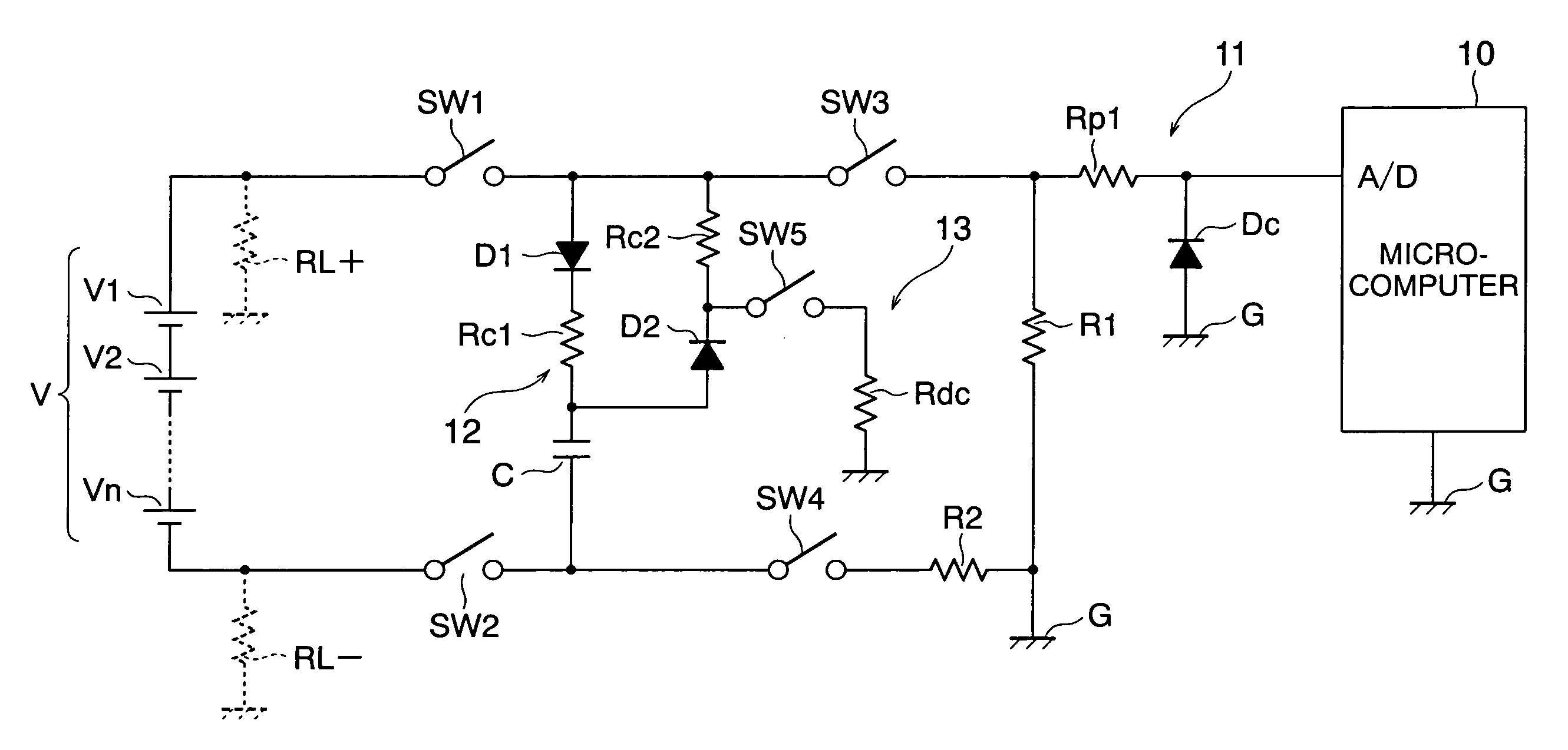
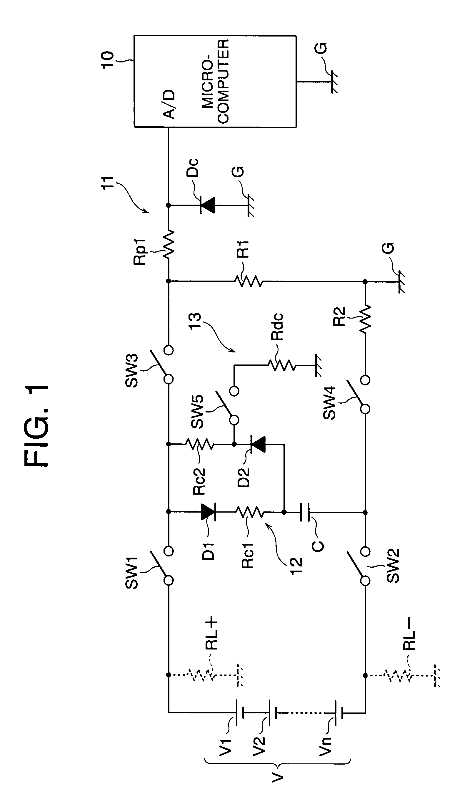
[0040]An insulation detecting apparatus as the voltage detecting apparatus according to the present invention will be described with reference to the drawings. FIG. 1 is a circuit diagram of one embodiment of the insulation detecting apparatus as the voltage detecting apparatus according to the present invention. A high-voltage power source V as a direct-current power source is formed by connecting batteries of N numbers in series and insulated from earth by a low-voltage system, such as a micro-computer 10.

[0041]As shown in FIG. 1, the insulation detecting apparatus includes a capacitor C, a micro-computer 10, a first switch SW1, a second switch SW2, a third switch SW3, a fourth switch SW4, a first resistor R1, a second resistor R2, a protection circuit 11, a resistor select circuit 12, and a reset circuit 13.

[0042]The capacitor C is a bipolar capacitor for measuring a voltage of a high-voltage power source by a flying-capacitor method.

[0043]The micro-computer 10 as a switch contro...


PUM


Abstract

A voltage detecting apparatus for detecting a voltage of a direct current power source by using a capacitor, which can process an abnormal voltage without elongation of measuring time. When a voltage between both terminals of the capacitor is greater than a maximum voltage in normal condition, a micro-computer discharges the capacitor through a third switch and a fourth switch to earth until the voltage between both terminals of the capacitor reduces to be not larger than a voltage corresponding to a maximum rated current of a reset switch. When the voltage between both terminals reaches to be not larger than the voltage corresponding to the maximum rated current, the capacitor is rapidly discharged through the reset switch by controlling the reset switch to be closed.

Description

[0001]The priority application Number Japan Patent Application 2006-267398 upon which this patent application is based is hereby incorporated by reference.BACKGROUND OF THE INVENTION[0002]1. Field of the Invention[0003]This invention relates to a voltage detecting apparatus, especially a voltage detecting apparatus for detecting a voltage of a direct current power source.[0004]2. Description of the Related Art[0005]As a voltage detecting apparatus for detecting a voltage of a direct current power source, there is generally, for example, a flying-capacitor-type insulation detecting apparatus. For detecting an insulating condition of an insulation condition of the high-voltage direct-current power source, a value of earth-fault resistance is calculated based on a measured value of a voltage between both terminals of an ungrounded capacitor (i.e. flying capacitor) charged with a voltage of the high-voltage power source and a measured value of a voltage between both terminals of the cap...

Claims


Application Information

Patent Timeline
Patent Type & Authority Patents(United States)
IPC IPC(8): G01R31/08
CPCG01R19/16542G01R27/18
Inventor HAYAKAWA, KENJIKAWAMURA, YOSHIHIRO
Owner YAZAKI CORP
Learn More