
System and method for suppressing IFF responses in the sidelobes and backlobes of IFF interrogator antennas

a technology of sidelobes and backlobes, which is applied in the field of system and method for suppressing iff responses in the sidelobes and backlobes of iff interrogator antennas, and can solve problems such as null degrees

Active Publication Date: 2010-04-27
TELEPHONICS
View PDF15 Cites 3 Cited by
  • Summary
  • Abstract
  • Description
  • Claims
  • Application Information

AI Technical Summary

Benefits of technology

[0016]The present invention is directed to an improved IFF system. The invention includes an antenna diversity method and system that compensates for the strong spatial back lobe present in small vertical aperture IFF antennas of the type typically used on aircraft. The present invention eliminates the “ghost” problem found in traditional IFF antennas. The present invention employs a Non-Reciprocal IFF antenna to modify the radiation patterns for Uplink and Downlink patterns so that the side lobe regions of the respective links are different. The use of a non-reciprocal antenna precludes the mirror image “ghost” without generating “ghosts” at other angles like the present art does. The present invention can be used in conjunction with ISLS and RSLS functions. When using ISLS and RSLS, the system of the present invention will only establish an IFF link in the main lobe region of the IFF antenna and will suppress links in the side lobes of the IFF antenna. The system of the present invention manipulates the sidelobes to preclude establishing either the uplink or the downlink.
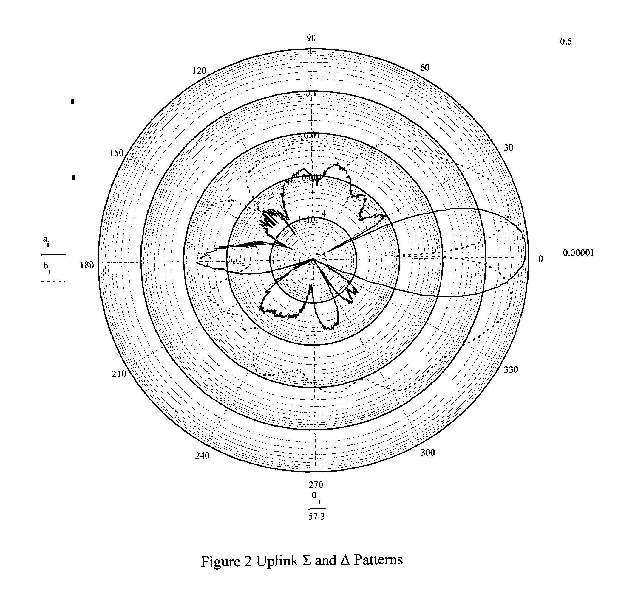
[0017]An IFF link is a round trip between two devices which includes an uplink and a downlink (Interrogator to Transponder and Transponder to Interrogator). For the link to be established in either direction, the sum beam gain (Σ) must be greater than the difference beam gain (Δ). The sum beam is the sum of the pattern that results from adding the power of the individual radiating elements in the array providing a mainlobe at zero degrees. The difference beam is the pattern that results by taking the difference between the sum of the individual radiating elements of the right half of the array and the sum of the individual elements of the left half of the array. This pattern results in a null at zero degrees. When the interrogator requests information from a target a “ghost” of the target may appear in the side lobe of the IFF antenna when the sum side lobe in the sum pattern exceeds the difference side lobe pattern and the angle at which this occurs is in the direction of a target. If this condition occurs, the interrogator will attempt to inadvertently create link with the target generating a “ghost”. An inadvertent link is one that the IFF system attempts to create with the ghost a real target. If, for any given angle outside the main lobe, either the uplink or the downlink is broken then the inadvertent IFF link at that angle is broken also, thus preventing the IFF system from wasting computing resources attempting to link with a specious ghost signal or the confusion to the operator of dealing with the same target in multiple locations. An example of a region outside the main lobe includes but is not limited to the side lobe and the back lobe. The present invention eliminates the “ghost” problem by making the signal sent by the IFF antenna non-reciprocal which allows the ghost to be distinguished from the actual target and thus eliminates the creation of inadvertent links.

Problems solved by technology

This pattern results in a null at zero degrees.

Method used


Image

  • System and method for suppressing IFF responses in the sidelobes and backlobes of IFF interrogator antennas
  • System and method for suppressing IFF responses in the sidelobes and backlobes of IFF interrogator antennas
  • System and method for suppressing IFF responses in the sidelobes and backlobes of IFF interrogator antennas

Examples


Embodiment Construction

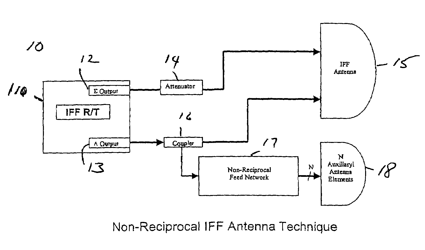
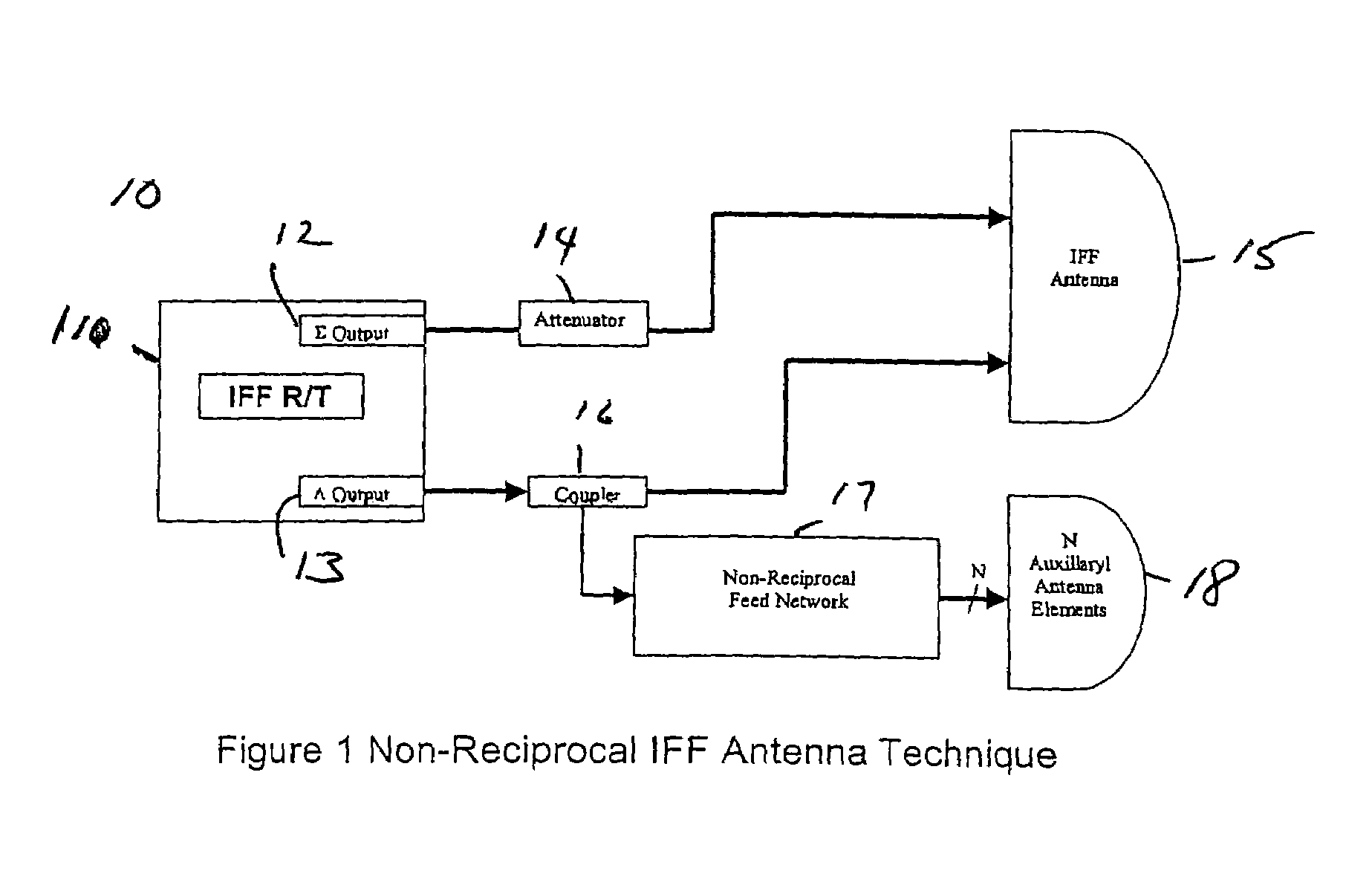
[0025]FIG. 1 depicts a representative block diagram for the system 10 employing a non-reciprocal antenna method of the present invention. The system includes an IFF Receiver / Transmitter 11 that generates an Σ signal 12 and a Δ signal 13. The Σ signal is sent to an Attenuator 14 and from there the Σ signal is then sent to the IFF Antenna 15. The number, type and configuration of the antennas making up the antenna may vary widely according to the particular application. However, in most aircraft, IFF antennas are small vertical aperture IFF antennas. The present invention is particularly advantageous with small vertical aperture IFF antennas. There may be one or more IFF antennas on the aircraft. Additionally, the overall height of the antenna(s) can vary as well. Where there are a plurality of antennas they can, if desired, be arranged in one or more rows. In one embodiment, where the number of rows of antenna elements is “n”, the total height of the antenna containing n rows can be ...


PUM


Abstract

An IFF interrogation system for use on an aircraft is described. The system transmits a signal from an interrogator to a transponder and from the transponder to the interrogator. The system includes a non-reciprocal IFF antenna that breaks either an uplink signal or a downlink signal at any given angle outside the main beam. The IFF transmitter transmits an Uplink Σ signal and an Uplink Δ signal to the IFF antenna.

Description

[0001]This is a conversion of U.S. Provisional Patent Application Ser. No. 60 / 588,461, filed Jul. 16, 2004, the disclosures of which are incorporated herein by reference.FIELD OF THE INVENTION[0002]The present invention relates to antennas in Interrogate Friend or Foe (IFF) Systems for implementing Interrogator Side Lobe Suppression (ISLS) and Receive Side Lobe Suppression (RSLS) functions in the rear hemisphere.BACKGROUND OF THE INVENTION[0003]Throughout time, it has always been important to know who one's friends are. Nowhere has this been more obvious than in military conflicts, where for centuries, flags, banners, insignia and uniforms have allowed adversaries to distinguish their cohorts from others who might have less friendly intentions. And, in darkness, when those visual means of identification were impossible, the business of using passwords and countersigns achieved the same end.[0004]That system worked for millennia as long as conflicts were more or less face to face and...

Claims


Application Information

Patent Timeline
Patent Type & Authority Patents(United States)
IPC IPC(8): G01S13/78
CPCG01S13/78G01S13/762
Inventor WAHL, ROBERT
Owner TELEPHONICS
Learn More