Microstrip array antenna

a microstrip array and array antenna technology, applied in the field of microstrip array antennas, can solve the problems of reducing the aperture efficiency of a reflector antenna, and only having an aperture efficiency of about 55%, and achieves the effect of high aperture efficiency and easy adaptation

Inactive Publication Date: 2010-04-27
SOUTHERN METHODIST UNIVERSITY
View PDF34 Cites 9 Cited by
  • Summary
  • Abstract
  • Description
  • Claims
  • Application Information

AI Technical Summary

Problems solved by technology

For example, they are bulky and relatively expensive for residential use.
Furthermore, inherent in reflector antennas are feed spillover and aperture blockage by a feed assembly, which significantly reduces the aperture efficiency of a reflector antenna, typically resulting in an aperture efficiency of only about 55%.
Microstrip array antennas, however, typically require a complex microstrip feed network which contributes significant feed loss to the overall antenna loss.
Furthermore, many microstrip array antennas are limited to single polarization and to transmitting or receiving only a linearly polarized beam.
Such a drawback is particularly significant in many parts of the world where broadcast services are provided using only circularly polarized beams.
In such instances, the recipients of the services must resort to less efficient and more expensive, bulky reflector antennas, or microstrip array antennas which utilize a polarizer.
A polarizer, however, introduces additional power loss to the antenna and produces a relatively poor quality radiation pattern.

Method used


Image

  • Microstrip array antenna
  • Microstrip array antenna
  • Microstrip array antenna

Examples


Embodiment Construction

[0043]In the following discussion of the drawings, certain depicted elements are, for the sake of clarity, not necessarily shown to scale, and like or similar elements are designated by the same reference numeral through the several views.

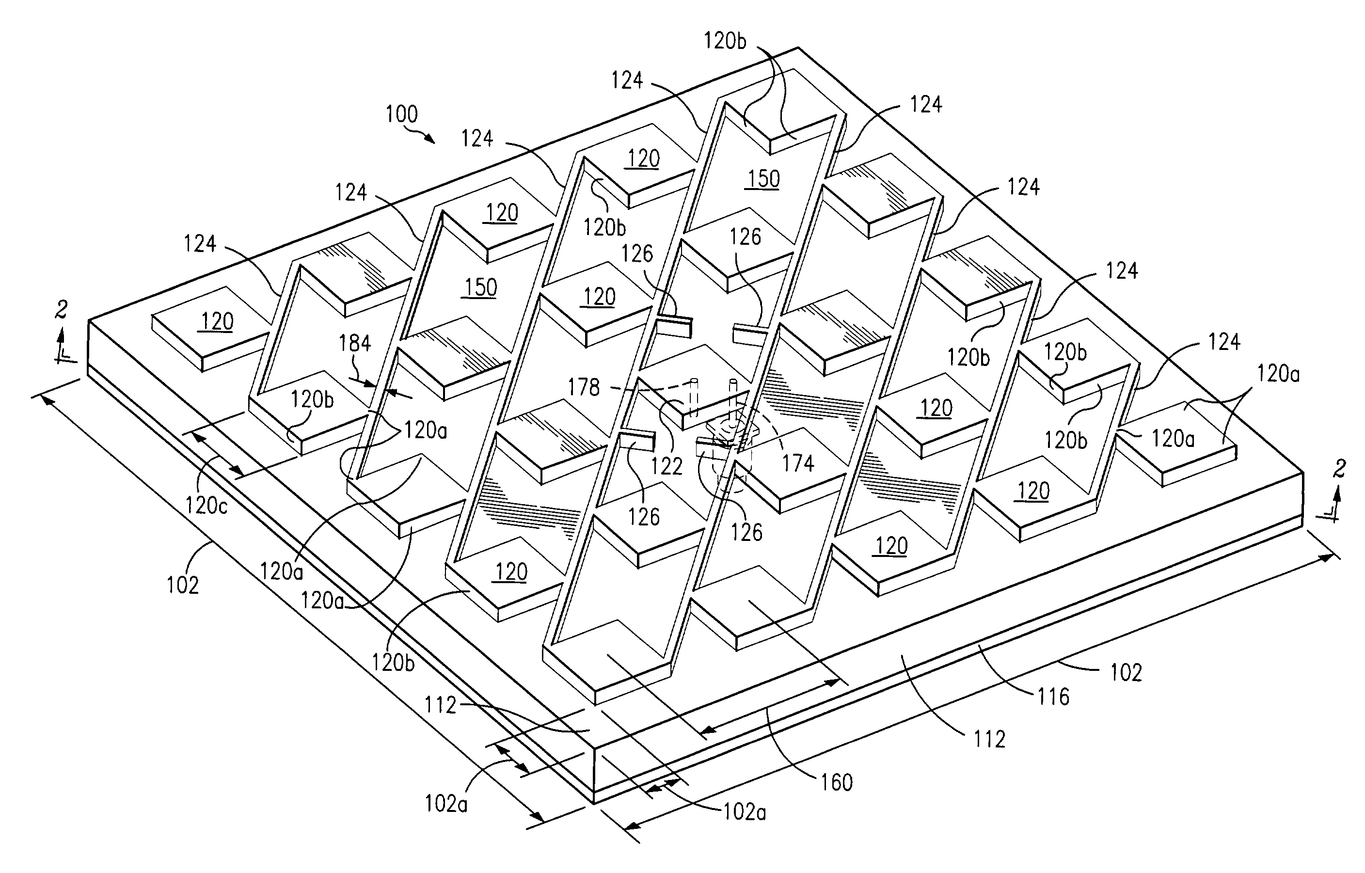
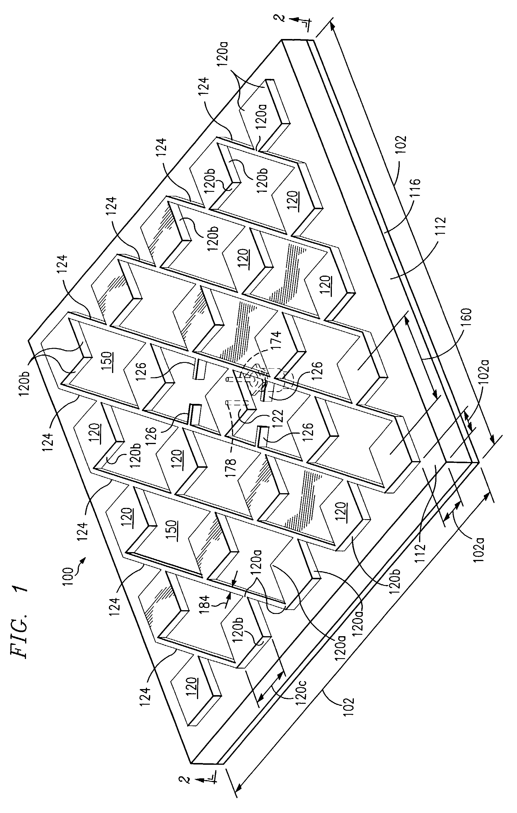
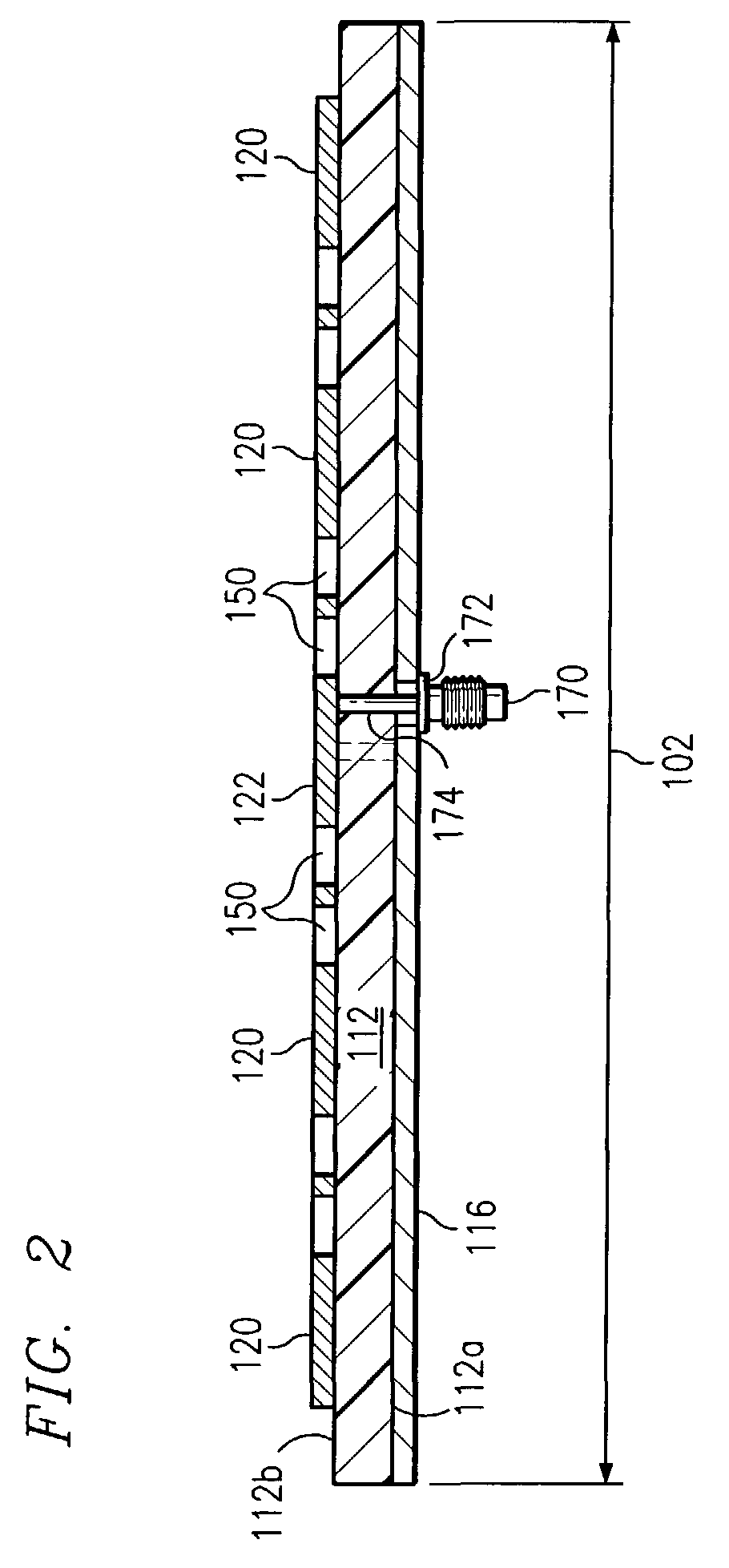
[0044]Two types of antennas are described hereinafter. One is a linearly polarized antenna that has one feed for a single-mode operation. In this embodiment, crisscrossing or intersecting stripline conductors are not required and the structure is simpler. The other is a dual-mode antenna with two input feeds that are operational independently each other and has crisscrossing or intersecting stripline conductors connecting the patches to the feed connectors.

[0045]In the dual mode configuration, the antenna acts as two antennas superimposed. Such an antenna may use two feed terminals with the stripline conductors of one terminal being orthogonal to the stripline conductors of the other terminal. Each of the patches in the antenna are connected at one...


PUM


Abstract

A microstrip antenna has a single dielectric layer with a conductive ground plane disposed on one side, and an array of spaced apart radiating patches disposed on the other side of the dielectric layer. The radiating patches are interconnected with a feed terminal via stripline elements. Responsive to electromagnetic energy, a high-order standing wave is induced in the antenna and a directed beam is transmitted from and / or received into the antenna. A dual-mode embodiment is configured such that standing wave nodes occur at the intersection of orthogonally situated striplines to minimize cross-polarization levels of the signals and the cross-talk between the two modes of operation.

Description

TECHNICAL FIELD[0001]A single dielectric layer multipatch, microstrip array antenna design contained in a leaky cavity, to distribute EM (electromagnetic) power between radiating patches and a feed source.BACKGROUND[0002]The invention relates generally to antennas and, more particularly, to microstrip array antennas.[0003]The number of direct satellite broadcast services has substantially increased worldwide and, as it has, the worldwide demand for antennas having the capacity for receiving such broadcast services has also increased. This increased demand has typically been met by reflector, or “dish,” antennas, which are well known in the art. Reflector antennas are commonly used in residential environments for receiving broadcast services, such as the transmission of television channel signals, from geostationary, or equatorial, satellites. Reflector antennas have several drawbacks, though. For example, they are bulky and relatively expensive for residential use. Furthermore, inhe...

Claims


Application Information

Patent Timeline
Patent Type & Authority Patents(United States)
IPC IPC(8): H01Q1/38H01Q21/06
CPCH01Q21/065
Inventor LEE, CHOON SAE
Owner SOUTHERN METHODIST UNIVERSITY
Why Eureka
Try Eureka