Modular integrated rail assembly for firearms

a module and integrated rail technology, applied in the direction of weapons, butts, weapon components, etc., can solve the problems of conflict between the unimpeded function of the gun barrel, the space on the upper receiver rail is limited, and the insufficient space on the integrated rail

Active Publication Date: 2010-05-04
SWAN RICHARD E
View PDF40 Cites 117 Cited by
  • Summary
  • Abstract
  • Description
  • Claims
  • Application Information

AI Technical Summary

Benefits of technology

[0017]When the upper hand guard is assembled with the upper receiver, the dovetail rail of the upper hand guard is arranged so that it extends forwardly in linear alignment with the dovetail rail of the upper receiver to form a continuous rail extending over the barrel. In order to provide automatic alignment of the dovetail rail on the upper hand guard with the dovetail rail on the upper receiver, alignment structures (tabs) are provided at the rear end of the upper hand guard. The alignment tabs extend rearwardly and are configured to engage the side walls of the upper receiver to provide automatic alignment during mounting and to prevent rotation of the upper hand guard relative to the upper receiver during use.
[0020]In another embodiment, the integrated rail system further includes an optional dovetail sleeve configured to be clamped onto the aligned dovetail rails of the upper receiver and upper hand guard. The upper surface of the sleeve includes a mil-std 1913 dovetail rail to provide an elevated optics platform while the lower surface includes a dovetail channel that rigidly clamps over the aligned dovetail rails of the upper receiver and upper hand guard to further prevent rotation of the upper hand guard relative to the upper receiver in the event of an impact.
[0021]Accordingly, among the objects of the present invention are: the provision of a new and improved modular integrated rail system for mounting a modular accessory onto a firearm without attaching either the rail system or the accessory directly to the gun barrel; the provision of a modular integrated rail system that supports the accessories without introducing loads or additional stresses into the barrel of the firearm; the provision of an extended longitudinal rail for mounting accessories that is co-planar and aligned with the existing dovetail rail on the upper receiver over the entire length of the top of the firearm; the provision of means for automatically aligning the dovetail rail of the upper hand guard with the dovetail rail of the upper receiver during mounting on the weapon; the provision of means for maintaining alignment of the dovetail rail of the upper hand guard with the dovetail rail of the upper receiver during use of the weapon; and the provision of an optional sleeve to be mounted over the receiver for added height if desired.

Problems solved by technology

However, space on the upper receiver rail is limited, and many military personnel often have multiple sighting devices that are each tailored to perform in different combat situations.
The difficulty is that there is simply not enough space on the integrated rail 30 provided on the upper receiver 14 to accommodate all of the desired accessories.
As can be appreciated, the problem in attempting to meet this requirement by integrating a variety of modular attachments onto firearms is the inherent conflict between the unimpeded function of the gun barrel 18 and the desirability to be able to use the barrel 18 and / or other parts of the weapon 10 as a mounting platform for the desired modular attachments.
The conflict arises from the fact that any additional weight and / or shocks that may be applied to the barrel from external attachments and accessories can adversely affect the alignment and reliable function of the weapon.
First, in operation, the temperature of a gun barrel can quickly rise to 900° F. This type of heat, as well as the physical shock transferred through the gun barrel during firing, can damage or destroy any attachments that are mounted in direct contact with the barrel.
Additionally, the heat generated by the gun barrel is transferred to any devices mounted thereon, such as hand guards, thereby resulting in the direct transfer of enough heat to burn a user's hands and to potentially interfere with the operation of other attachments.
The second issue compounding this problem is that if accessories are to be supported by the gun barrel, the gun barrel may need to be enlarged to support the added weight and shock forces.
For example, a grenade launcher attachment not only introduces additional weight to the barrel, it also introduces substantial recoil in operation that is transferred into the firearm through the barrel.
The combination of heat and force applied to the barrel tends to pull the barrel chamber out of alignment with the bolt lead, thereby causing bolt lug and extractor failure, ultimately jamming the firearm.
In the case of a grenade launcher, the weight is considerable and could affect performance of the weapon.
However, it has been noted in field use that the dovetail sleeve introduces an added height to the existing mil-std 1913 rail of the receiver, and that this added height is not always desirable, particularly for some sighting devices that are popular with the military.

Method used


Image

  • Modular integrated rail assembly for firearms
  • Modular integrated rail assembly for firearms
  • Modular integrated rail assembly for firearms

Examples


Embodiment Construction

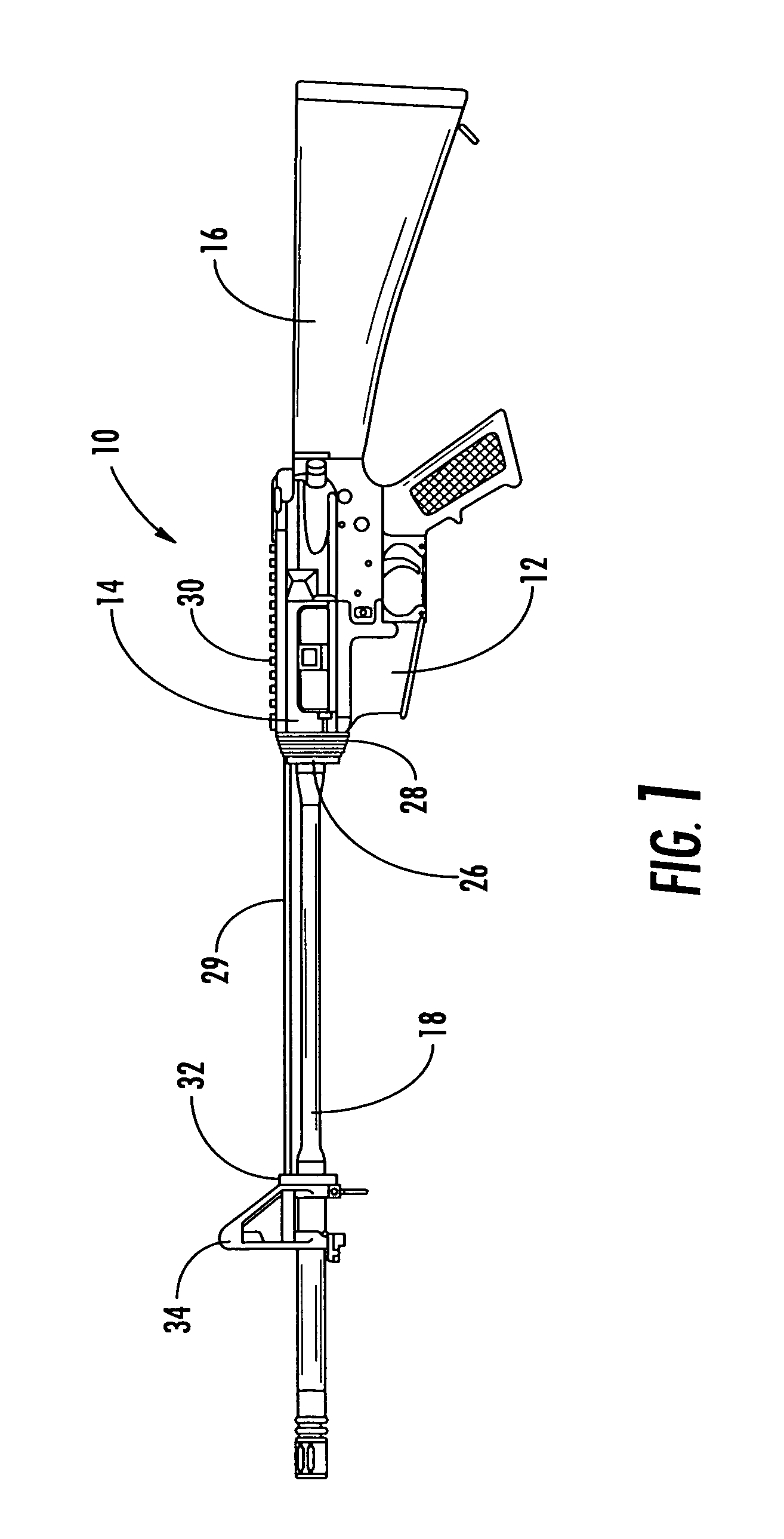
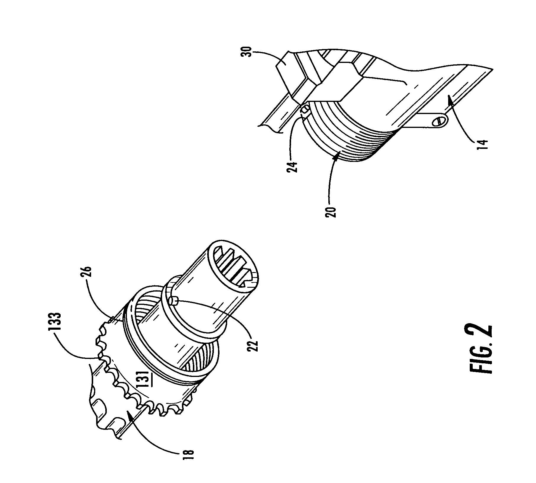
[0045]Now referring to the drawings in detail, the modular integrated rail system of the instant invention is illustrated and generally indicated at 100 in FIGS. 3-15. As will hereinafter be more fully described, the present rail system 100 as illustrated is adapted for use with a conventional M4 / M16 firearm 10 (M4 and M16 are trademarks of Colt Defense, LLC). However, it should be understood that the rail system 100 can be easily adapted for use with other firearms, and the disclosure herein should not limited to the M16 / M4 weapon platform.

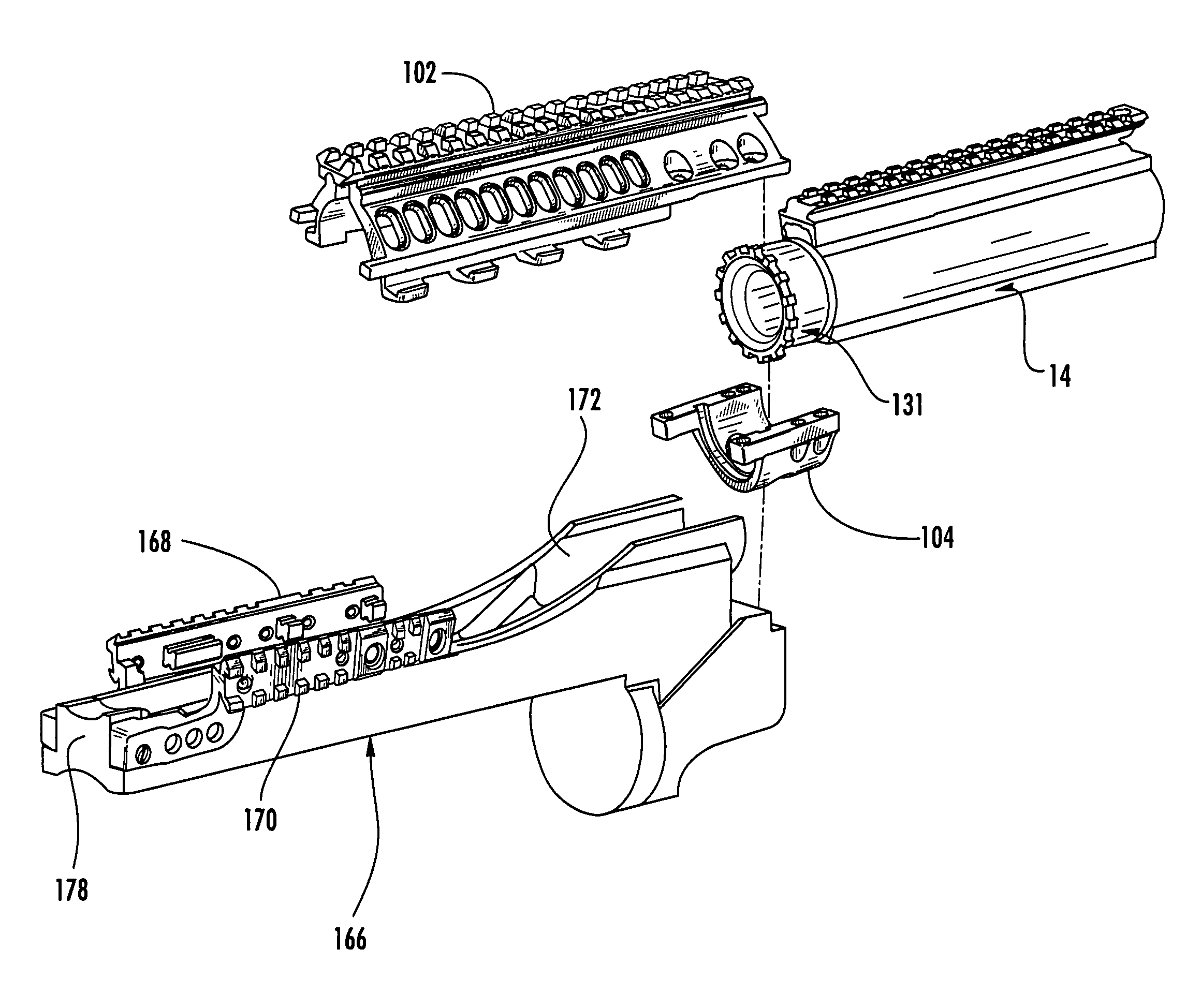
[0046]As best shown in FIG. 10A, the modular integrated rail system 100 includes an upper hand guard generally indicated at 102, a clamp generally indicated at 104, a lower firearm accessory generally indicated at 106, and an optional dovetail sleeve generally indicated at 108.

[0047]Referring to FIGS. 3-7, the upper hand guard 102 is the main structural element of the modular integrated rail system 100. The upper hand guard 102 is generally semi-...


PUM


Abstract

A modular integrated rail system for a firearm includes an upper hand guard having a dovetail rail extending longitudinally between the forward end and the rearward end thereof. The rearward end of the upper hand guard includes a clamp that removably secures the upper hand guard to the barrel nut of the firearm. The rearward end of the upper hand guard and the clamp include clamping surfaces configured to cooperatively engage the outer surface of the barrel nut. The upper hand guard further includes mounting channels that are used to mount accessories, such as a lower hand guard or a grenade launcher, to the upper hand guard. The rear end of the upper hand guard includes alignment tabs for automatically aligning the dovetail rail of the upper hand guard with the dovetail rail of the upper receiver during mounting. The tabs also prevent rotation of the rail system relative to the upper receiver during use.

Description

CROSS-REFERENCE TO RELATED APPLICATIONS[0001]This application is related to and claims priority from earlier filed U.S. Provisional Patent Application No. 60 / 641,694, filed Jan. 5, 2005.[0002]This application is a continuation-in-part of U.S. application Ser. No. 29 / 237,440, filed Aug. 31, 2005, now U.S. Pat. No. D,544,564.BACKGROUND OF THE INVENTION[0003]The present invention relates generally to modular interface assemblies for weapons. More specifically, the present invention relates to a modular interface assembly that includes a rail system, which is clamped around and supported by the barrel nut of a firearm and further includes an optional sleeve element that can be installed to extend from the upper receiver rail over the top of the clamped rail system.[0004]As the field of combat and commercial weaponry expands, numerous add-on enhancements have become available for attachment to standard firearms, thereby significantly upgrading the capability of the firearm. Of particular...

Claims


Application Information

Patent Timeline
Patent Type & Authority Patents(United States)
IPC IPC(8): F41C27/06F41C27/00
CPCF41G11/003F41C23/16
Inventor SWAN, RICHARD E.
Owner SWAN RICHARD E
Why Eureka
Try Eureka