Endoscope and related system

a technology of endoscope and related system, which is applied in the field of high-definition endoscopes, can solve the problems of surgical invasiveness and obstruction of fluid flow

Active Publication Date: 2010-05-04
LINVATEC
View PDF57 Cites 45 Cited by
  • Summary
  • Abstract
  • Description
  • Claims
  • Application Information

AI Technical Summary

Problems solved by technology

However, the increased size, surgical invasiveness, and obstruction in fluid flow that results from increasing the diameter of the objective lens or objective lens assembly in the endoscope weighs against such an approach.

Method used


Image

  • Endoscope and related system
  • Endoscope and related system
  • Endoscope and related system

Examples


example

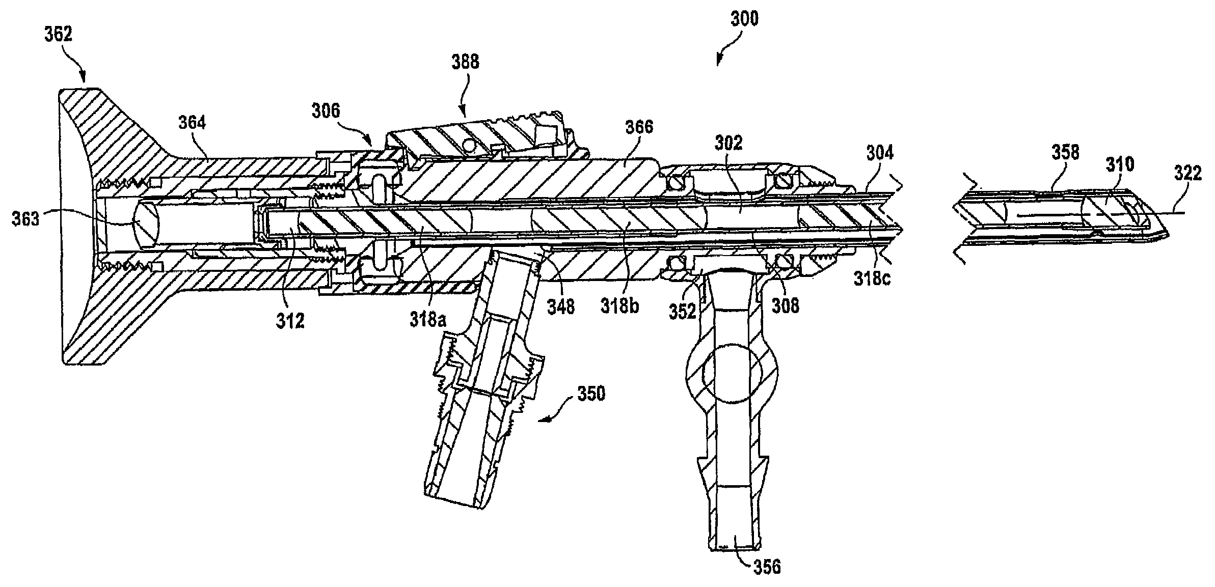
[0070]In an example of an endoscope-sheath system according to the invention, the endoscope and sheath couple together and collaborate in use. The endoscope consists of image relay optics with an objective lens at the distal end, an image relay intermediate, and an ocular at the proximal eyecup. When coupled to a camera head, the image may be sensed by an image pickup device such as a CCD.

[0071]The scope, consisting of image optics only (no illumination fibers), houses the optic elements in an elongated hollow shaft of minimum diameter, which is dictated by the size of the optics and the tube thinness. However, the objective lens may be oversized with respect to the majority of the tip length as to provide greater optical performance. Since the majority of tip length is of minimum diameter, fluid irrigation, in the annular space between the scope and sheath, is accommodated with minimum sheath size.

[0072]The scope has a distal end of larger diameter wherein the objective lens(es) ar...


PUM


Abstract

An endoscope is described in which the diameter of the image relay assembly is less than that of the objective lens assembly. An endoscope sheath is also described for sheathing the endoscope and housing or directing optical fibers for use in illuminating the endoscope view of view. An endoscope-sheath system is further described comprising the combination of the endoscope and the endoscope sheath in eccentric alignment to reduce fluid flow impedance between the two.

Description

[0001]This application claims the benefit of U.S. Provisional Application Ser. No. 60 / 570,276, filed May 12, 2004, and U.S. Provisional Application Ser. No. 60 / 590,480, filed Jul. 22, 2004, both of which are hereby fully incorporated by reference herein as though set forth in full.[0002]This application is a continuation-in-part of U.S. patent application Ser. No. 10 / 918,187 filed Aug. 13, 2004, now U.S. Pat. No. 7,160,247, which is hereby incorporated by reference herein as though set forth in full.BACKGROUND[0003]1. Field of the Invention[0004]This invention relates to the field of endoscopes, and, more specifically, high definition endoscopes that allow higher resolution viewing of internal body structures compared to conventional endoscopes.[0005]2. Related Art[0006]A high definition endoscope is needed to allow higher resolution viewing of internal body structures in relation to conventional endoscopes, and to match that available in current broadcast cameras. However, the incr...

Claims


Application Information

Patent Timeline
Patent Type & Authority Patents(United States)
IPC IPC(8): A61B1/12A61B1/00A61B1/015A61B1/04A61B1/055A61B1/06
CPCA61B1/04A61B1/015A61B1/00165A61B1/055
Inventor DEPPMEIER, THOMAS R.SPEIER, CRAIG J.VERKAIK, JOSIAH E.WALLS, ROBERT R.
Owner LINVATEC
Why Eureka
Try Eureka