Integrated insulator seal and shield assemblies

a technology of integrated insulators and shield assemblies, which is applied in the direction of overvoltage protection resistors, emergency protective arrangements for limiting excess voltage/current, circuit arrangements, etc., can solve the problems of inability to properly install devices, decrease the speed and efficiency with which corona protection devices may be installed, and achieve the effect of effectively bonding rubber housings and metal fittings

Active Publication Date: 2010-05-04
HUBBELL INC
View PDF19 Cites 18 Cited by
  • Summary
  • Abstract
  • Description
  • Claims
  • Application Information

AI Technical Summary

Benefits of technology

[0012]By forming the insulator sealing and shielding assembly in this manner, a sealant can be dispensed into one of the apertures until the collar assembly is full of sealant to create a first seal. Three additional sealing surfaces protect the initial seal against moisture ingress and seal the flow channel to effectively bond the rubber housing and metal fitting.

Problems solved by technology

One of the problems with conventional corona protection devices is the number of parts required to assemble the corona protection device, thereby increasing the manufacturing costs.
Additionally, an installer must transport more parts to a job site, which decreases the speed and efficiency with which the corona protection devices may be installed.
Since existing corona protection devices require various parts in order to completely assemble the device, if one part is lost or missing, the device cannot be properly assembled.
Other problems with existing corona protection devices involve poor seals being formed between the corona protection device and the insulator, as well as the corona protection device being poorly secured to the insulator.
Inadequate seals and connections to the insulators result in a highly ineffective corona protection device, often resulting in failure of the corona protection device.

Method used


Image

  • Integrated insulator seal and shield assemblies
  • Integrated insulator seal and shield assemblies
  • Integrated insulator seal and shield assemblies

Examples


Embodiment Construction

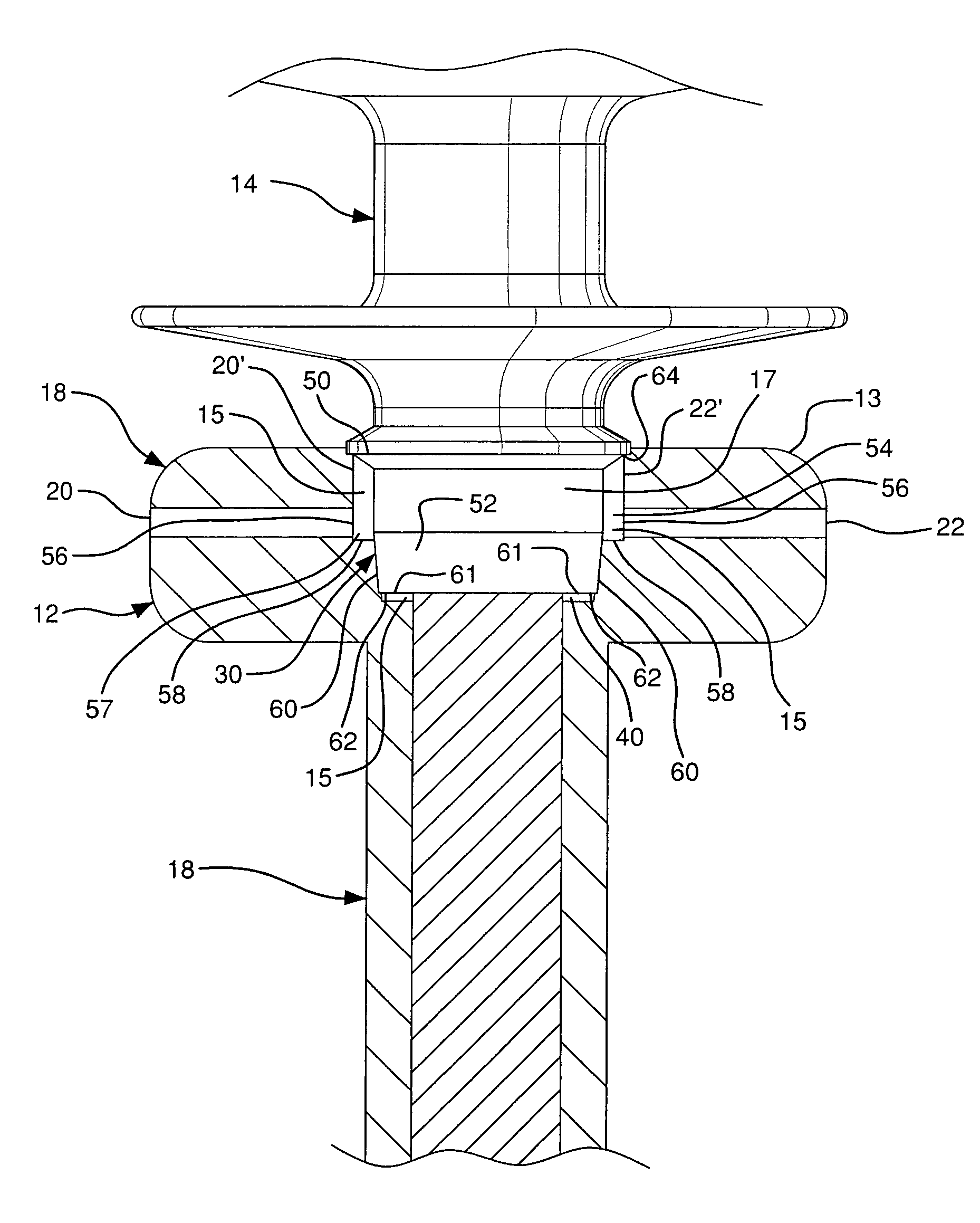
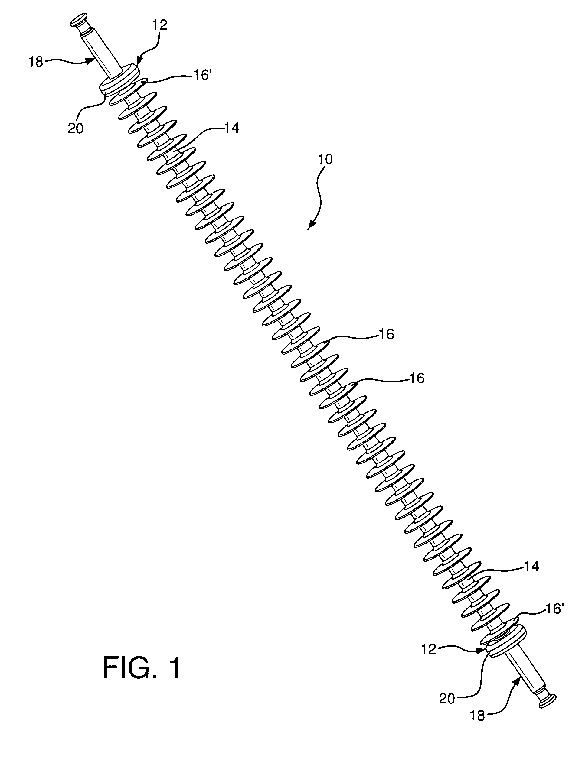
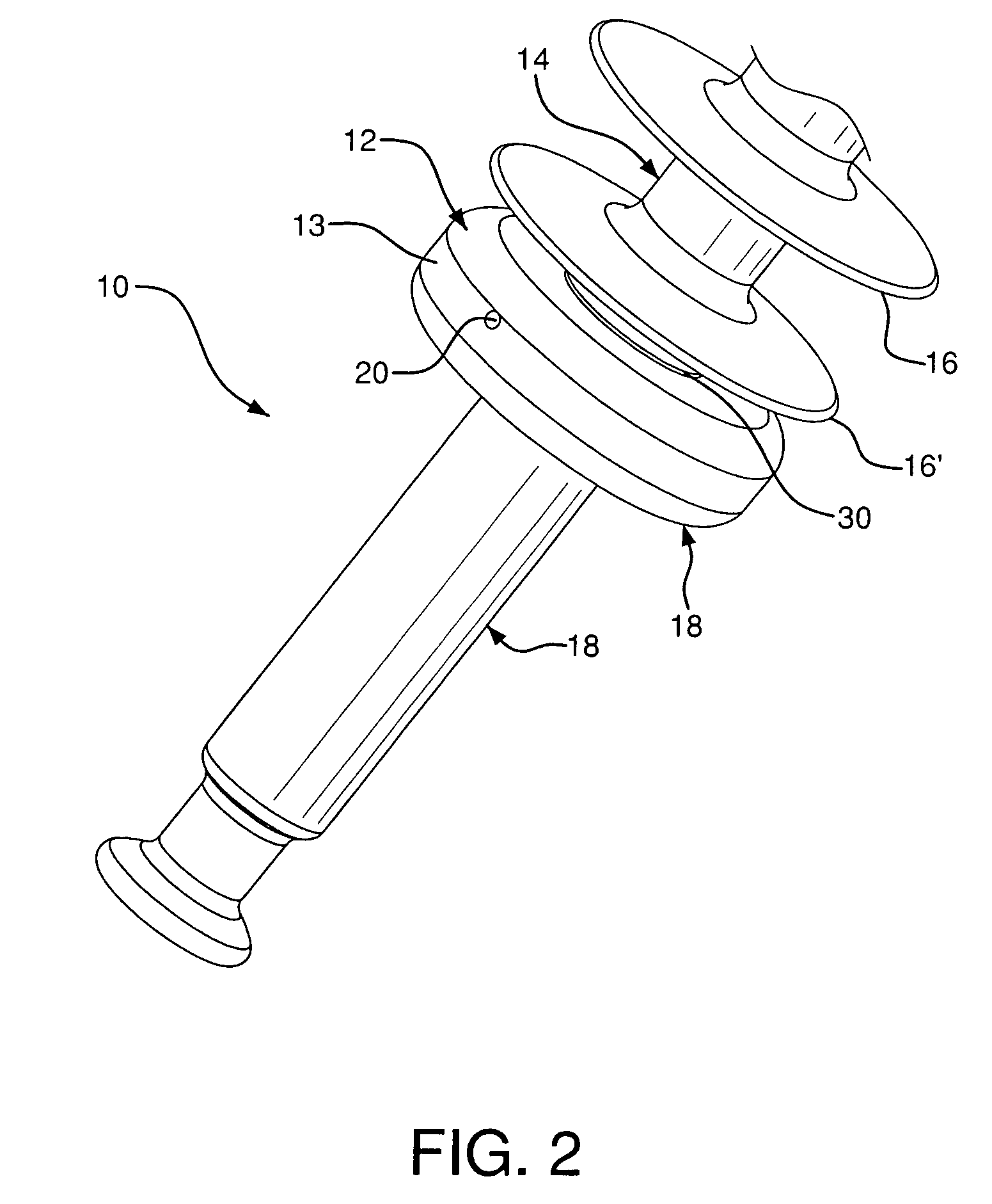
[0021]Referring to FIGS. 1-4, an insulator sealing and shielding assembly 10 includes an annular collar assembly 12 disposed below a tubular rubber or polymer housing 14 with a plurality of weathersheds 16, and a metal fitting 18 with a collar assembly 12 at each end of the rubber housing 14. The rubber housing 14 includes a plurality of radial weathersheds 16 evenly disposed about the housing 14 in a columnar arrangement. The extended portion of each metal fitting 18 away from the weathershed housing is disposed on the opposite side of the collar assembly 12 relative to the rubber housing 14.

[0022]Ultimately, the rubber housing 14 is adapted to be inserted into and connected to each metal fitting 18 under pressure. Since each metal fitting 18 and collar assembly 12 is identical, only one will be described in detail.

[0023]The weathersheds 16 are spaced apart equal distances from one another along the body of the insulator assembly 10. All weathersheds 16 have the same diameter. At t...


PUM

PropertyMeasurementUnit
distanceaaaaaaaaaa
radial distanceaaaaaaaaaa
temperatureaaaaaaaaaa

Abstract

An integrated insulator sealing and shielding assembly includes a rubber housing having a plurality of radial weathersheds and a tapered end adjacent an endmost radial weathershed. A metal fitting is disposed adjacent to the endmost radial weathershed and receives the tapered end. A collar assembly is disposed at an upper end of the metal fitting and includes two apertures between an outer surface thereof and the rubber housing for receiving a sealant. At least one sealing surface, preferably four, is disposed between the collar assembly and a bottom end of the rubber housing for securing the connection therebetween.

Description

FIELD OF THE INVENTION[0001]The present invention relates to a collar assembly for an integrated insulator sealing and shielding assembly. More particularly, the invention represents an integrated insulator sealing and shielding assembly with a rubber housing having a plurality of radial weathersheds and a tapered end adjacent to the endmost radial weathershed. A metal fitting is disposed adjacent to the endmost radial weathershed and receives the tapered end of the rubber housing. A collar assembly surrounds the connection between the metal fitting and the rubber housing. The collar assembly further includes two apertures between an outer surface thereof and the rubber housing for receiving a sealant. There are preferably multiple sealing surfaces disposed between the collar assembly and a bottom end of the rubber housing for securing the connection therebetween.BACKGROUND OF THE INVENTION[0002]Electrical polymer insulators are used in power transmission and distribution systems to...

Claims


Application Information

Patent Timeline
Patent Type & Authority Patents(United States)
IPC IPC(8): H01B17/42
CPCH01B17/44H01B17/10
Inventor BERNSTORF, ROBERT A.VAN BESOUW, BASTIAAN H.
Owner HUBBELL INC
Why Eureka
Try Eureka